BT
GENERATOR
TROUBLESHOOTING
EXCITER
ROTOR/FIELD
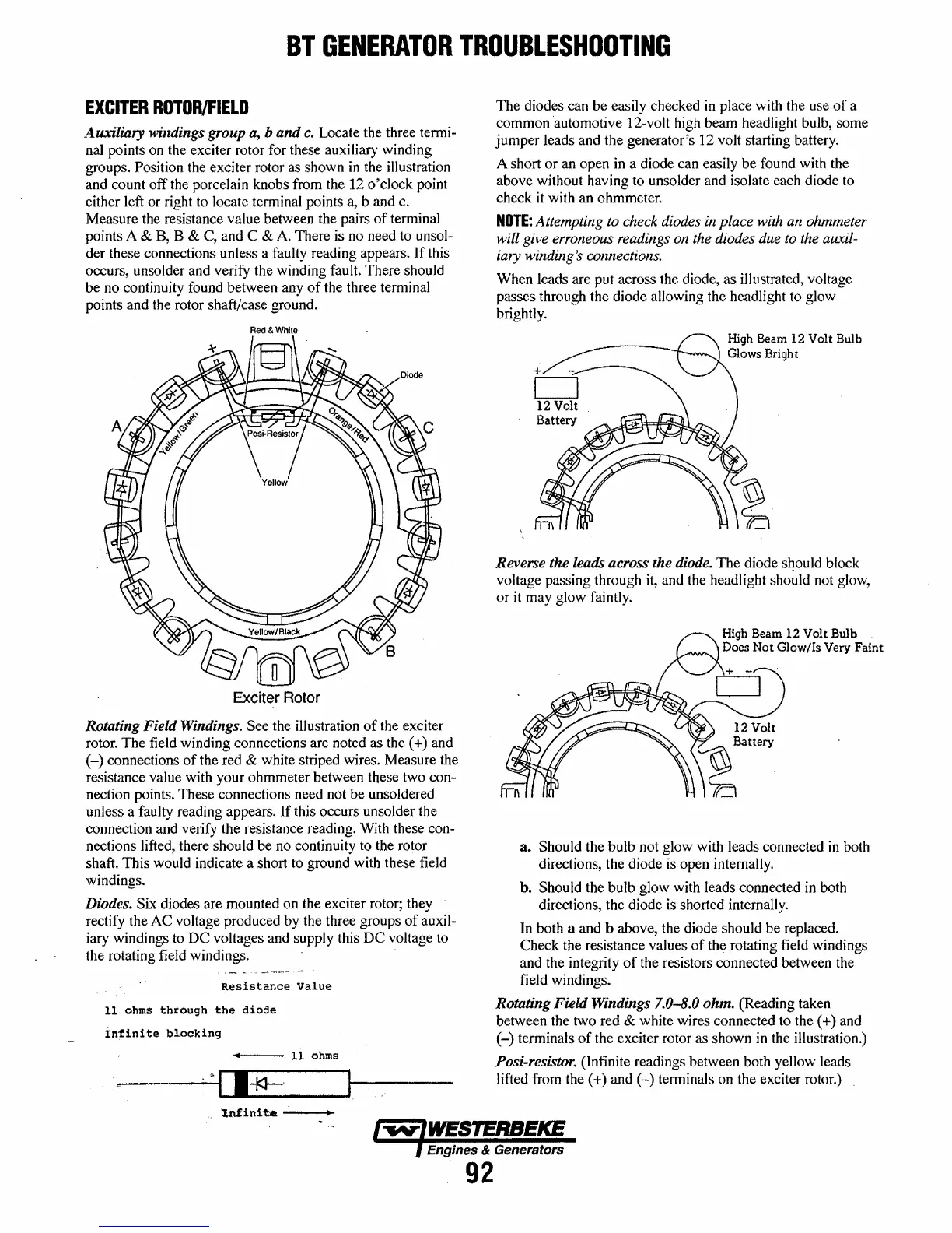
Auxiliary
windings group a,
band
c.
Locate the three termi-
nal points on the exciter rotor for these auxiliary winding
groups. Position the exciter rotor as shown
in
the illustration
and count off the porcelain knobs from the 12 o'clock point
either left or right to locate terminal points a,
band
c.
Measure the resistance value between the pairs
of
terminal
points A
& B, B & C, and C &
A.
There is no need to unsol-
der these connections unless a faulty reading appears.
If
this
occurs, unsolder and verify the winding fault. There should
be no continuity found between any
of
the three terminal
points and the rotor shaft/case ground.
Red & White
Exciter
Rotor
Rotating Field Windings. See the illustration
of
the exciter
rotor. The field winding connections are noted as the (+) and
(-)
connections
of
the red & white striped wires. Measure the
resistance value with your ohmmeter between these two
con-
nection points. These connections need not be unsoldered
unless a faulty reading appears.
If
this occurs unsolder the
connection and verify the resistance reading. With these con-
nections lifted, there should be no continuity to the rotor
shaft. This would indicate a short to ground with these field
windings.
Diodes. Six diodes are mounted on the exciter rotor; they
rectify the AC voltage produced by the three groups
of
auxil-
iary windings to
DC
voltages and supply this
DC
voltage to
the rotating field windings.
Resistance
value
11 ohms
through
the
diode
Infinite
blocking
...---
11 ohms
_----t'.>
I I*-'
"l.nfin!
ta
---+-
The diodes can be easily checked
in
place with the use
of
a
common automotive 12-volt high beam headlight bulb, some
jumper leads and the generator's 12 volt starting battery.
A short or an open in a diode can easily be found with the
above without having to unsolder and isolate each diode to
check
it
with an ohmmeter.
NOTE:
Attempting to check diodes in place with an ohmmeter
will give erroneous readings on the diodes due to the auxil-
iary winding's connections.
When leads are put across the diode, as illustrated, voltage
passes through the diode allowing the headlight to glow
brightly.
Reverse the leads across the diode. The diode
SDould
block
voltage passing through it, and the headlight should not glow,
or
it
may glow faintly.
High Beam 12 Volt Bulb
Does Not Glow/Is Very Faint
a.
Should the bulb not glow with leads connected
in
both
directions, the diode is open internally.
h.
Should the bulb glow with leads connected
in
both
directions, the diode is shorted internally.
In both a and b above, the diode should be replaced.
Check the resistance values
of
the rotating field windings
and the integrity
of
the resistors connected between the
field windings.
Rotating
Field
Windings 7.0-8.0
ohm.
(Reading taken
between the two red
& white wires connected to the (+) and
(-)
terminals
of
the exciter rotor as shown
in
the illustration.)
Posi-resistor. (Infinite readings between both yellow leads
lifted from the
(+)
and
(-)
terminals on the exciter rotor.)
Engines & Generators
92
 Loading...


