WMD
GENERATOR
DESCRIPTION
The
WMD
model generator is a self-exciting and self-regu-
lating brush style generator, requiring only a driving force to
produce voltage. It is four lead reconnectable for 115 volts or
115/230 volts, and has a four pole revolving armature with
no
DC
brushes
or
commutator.
It
has a solid state bridge rec-
tifier
in
the exciter circuit, AC slip rings, a drip-proof con-
struction, and a single bearing design. Voltage regulation is
7% no-load to full-load, and frequency regulation is
3-4
hertz no-load to full-load. It is
in
insulation class
"F"
as
defined by MEMA MGI-1.65, and it's temperature rise is
within MEMA
MGI-22.40 definition when operating at full-
load. It's centrifugal-type blower fan is direct connected
to
the armature shaft for cooling. Capacitors across the hot leg
and neutral minimize radio interference within the limits
of
most commercial and civilian applications. The armature is
balanced laminated steel, double dipped and baked. The field
ring is thick hot rolled steel with a welded bearing support
bracket, machined as an assembly for precise bearing align-
ment. The rear carrier bearing is pre-lubricated, double sealed
with an anti-rotation lock.
WMD
GENERATOR
SPECIFICATIONS
FREQUENCY
60
HERTZ
STANDARD
RPM
1800
for
60
Hertz
NOTE:
To
convert a 60 Hz
1500
for
50
Hertz
unit to 50
Hz,
the armature
must
be
changed.
Voltage
Normal
115VAG
230
VAG
Maximum
132
VAG
264
VAG
Minimum
108
VAG
216
VAG
Excitation
Voltage
115
VAG
(output
voltage
supplied
to
rectifier)
Field
Excitation
Voltage
190
VDG
(approximate)
DISASSEMBLY
1.
Lift and support the back end
of
the engine so that the
generator is not resting on its isolators.
2. Remove the generator endbell cover. This exposes the fan
and brush rig assembly. Remove the fan assembly with
its hardware.
3. Remove the brush rig assembly. This can be done in two
half assemblies.
Unbolt the two half-moon assemblies
from the frame attachment and lift the two halves away
from the slip rings. Mark the polarity
of
the two leads on
the bridge rectifier that go to the field coils and unplug
these from the bridge rectifier. The two half-moon brush
assemblies can be removed from the generator by remov-
ing the heavy output leads G 1, G2, G3 and G4 from their
attachment point on each brush holder. Make a rough
sketch as to where each
of
these leads attaches on each
assembly half. There are 8 leads that are paired
in
the
control panel to provide four reconnectable leads. Inspect
and replace components
in
the brush rig as needed. Do
not totally disassemble as this is not
n,eeded.
4. Remove the control panel from the top
of
the generator
housing. Mark all leads as needed for proper assembly.
5.
Unbolt the generator housing from the bell housing. A
puller may be needed at the bearing end to assist
in
pulling
the housing with or without the bearing off the armature.
Some gentle prying at the bell housing end will be needed
as well. The housing
with field coils is heavy. Once the
housing has cleared the armature shaft,
it
should be sup-
ported and slowly drawn over the armature. Try not to
drag
it
over the armature.
INSPECTION
1. Inspect the bearing and replace as needed. If the unit is
going through a major overhaul, bearing replacement is
recommended.
2. Check the field coils resistance values. Remove the field
coils from the housing. Note and mark each field coil's
position
in
the housing. Do not mix them
up!
Each coil has
a different part number and a specific position
in
the hous-
ing. Incorrect assembly will cause low voltage output.
3. Unbolt the armature from the flywheel. Test the armature
with an ohmmeter. Clean the slip rings and polish using a
crocus cloth.
REASSEMBLY
Reassemble
in
reverse order.
NOTE:
When
assembling
the
housing onto
the
generator
arma-
ture,
be
sure
to
properly
align
the
anti-slip
groove
in
the
bear-
ing
with
the hole
in
the
housing and install a new lock pin.
The fan on the back end plays an important part
in
moving
air through the generator for cooling.
In
installations where
surrounding air is limited, outside air should be ducted to the
area
of
the screened endbell inlet to provide this needed air
for cooling, and combustion as well.
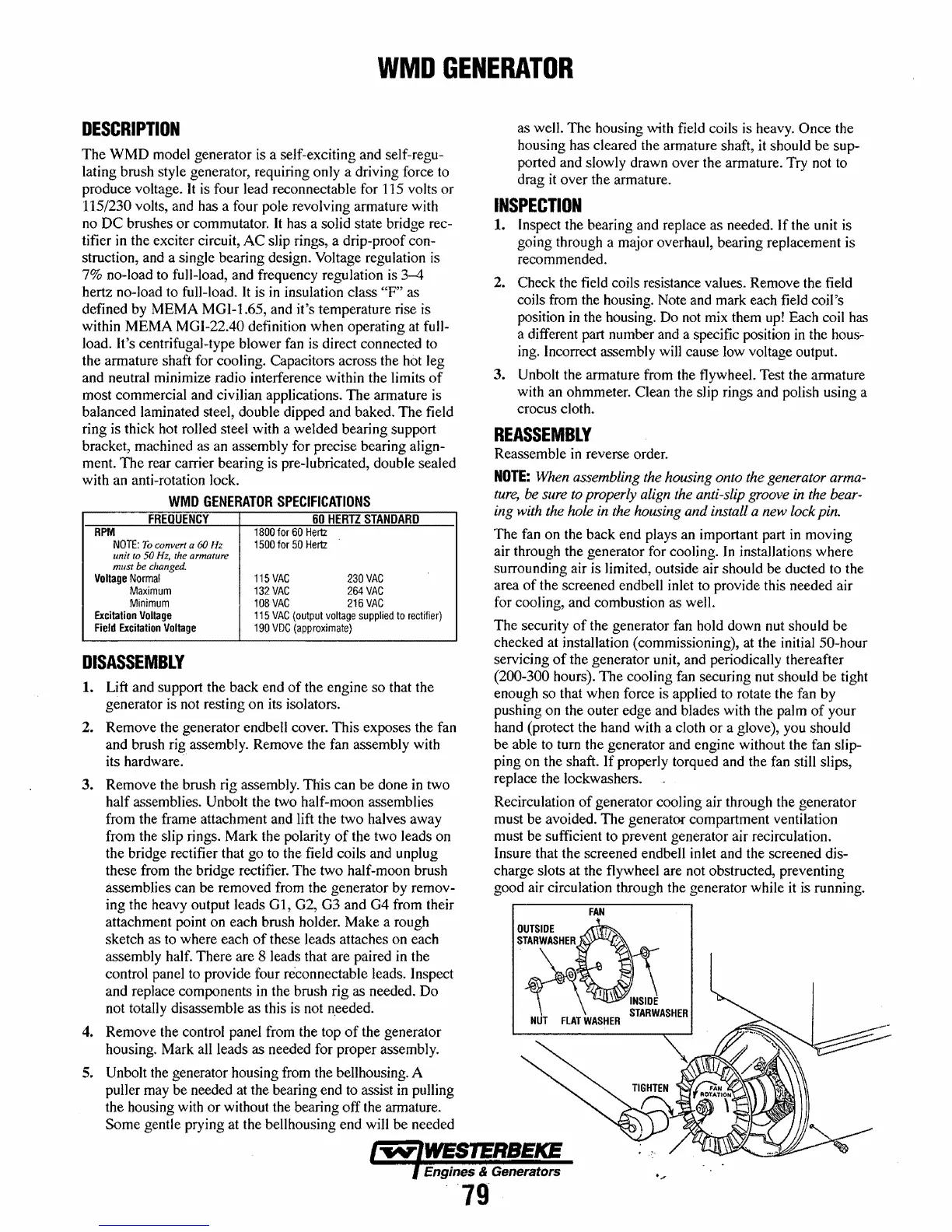
The security
of
the generator fan hold down nut should be
checked at installation (commissioning), at the initial
50-hour
servicing
of
the generator unit, and periodically thereafter
(200-300 hours). The cooling fan securing nut should be tight
enough so that when force is applied to rotate the fan by
pushing on the outer edge and blades with the palm
of
your
hand (protect the hand with a cloth
or
a glove), you should
be able to tum the generator and engine without the fan slip-
ping on the shaft.
If
properly torqued and the fan still slips,
replace the lockwashers.
Recirculation
of
generator cooling air through the generator
must be avoided. The generator compartment ventilation
must be sufficient to prevent generator air recirculation.
Insure that the screened endbell inlet and the screened dis-
charge slots at the flywheel are not obstructed, preventing
good air circulation through the generator while
it
is running.
FAN
~~03
NUT
flAT
WASHER
STARWASHER
Engines & Generators
'",
79
 Loading...


