ENGINE
ADJUSTMENTS
TIGHTENING
THE
CYLINDER
HEAD
Pull
off
the air breather pipe from the rocker cover and
remove the rocker cover. Before adjusting the valve clear-
ance, retighten the cylinder head bolts to their specified
torque
in
the sequence shown in the diagram. Make sure the
engine is cold when this is done. Before applying the speci-
fied torque
to
a bolt, loosen
it
1/4 to 1/2 a turn and then apply
the torque (see
TECHNICAL
DA1'4.).
¢
CD
CD
®
®
FRONT
CD
CD
CD
®
CD
cb
CD
CD
CYLINDER
HEAD
BOLT
TIGHTENING
SEQUENCE
ADJUSTING
VALVE
CLEARANCE
ADJUSTING
SCREW
LOCKNUT
CLEARANCE
(COLD)
0.25
MM
ADJUSTING
VALVE
Cl.EAR4NCE
1.
Adjust the valve clearances at
mc
(Top Dead Center)
for each cylinder when they are on their compression
stroke.' Remember the engine's firing order is 1-3·:4-2.
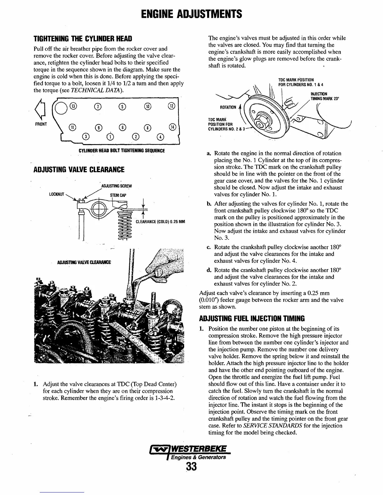
The engine's valves must be adjusted in this order while
the valves are closed.
You
may find that turning the
engine's crankshaft is more easily accomplished when
the engine's glow plugs are removed before the crank-
shaft is rotated.
a. Rotate the engine in the normal direction
of
rotation
placing the
No.1
Cylinder at the top
of
its compres-
sion stroke. The
mc
mark on the crankshaft pulley
should be in line with the pointer on the front
of
the
gear case cover, and the valves for the
No.1
cylinder
should be closed. Now adjust the intake and exhaust
valves for cylinder
No.1.
h.
After adjusting the valves for cylinder
No.1,
rotate the
front crankshaft pulley clockwise
180
0
so the
IDC
mark on the pulley is positioned approximately in the
position shown
in
the illustration for cylinder
No.3.
Now adjust the intake and exhaust valves for cylinder
No.3.
c.
Rotate the crankshaft pulley clockwise another 180
0
and adjust the valve clearances for the intake and
exhaust valves for cylinder
No.4.
d.
Rotate the crankshaft pulley clockwise another 180
0
and adjust the valve clearances for the intake and
exhaust valves for cylinder
No.2.
Adjust each valve's clearance by inserting a 0.25 mm
(0.010") feeler gauge between the rocker arm and the valve
stem as shown.
ADJUSTING
FUEL
INJECTION
TIMING
1.
Position the number one piston at the beginning
of
its
compression stroke. Remove the high pressure injector
line from between the number one cylinder's injector and
the injection pump. Remove the number one delivery
valve holder. Remove the spring below it and reinstall the
holder. Attach the high pressure injector line to the holder
and have the other end pointing outboard
of
the engine.
Open the throttle and energize the fuel lift pump. Fuel
should flow out
of
this line. Have a container under
it
to
catch the fuel. Slowly turn the crankshaft in the normal
direction
of
rotation and watch the fuel flowing from the
injector line. The instant
it stops is the beginning
of
the
injection point.
Observe the timing mark on the front
crankshaft pulley and the timing pointer on the front gear
case. Refer to
SERVICE STANDARDS for the injection
timing for the model being checked.
Engines & Generators
a3
 Loading...


