BT
GENERATOR
TROUBLESHOOTING
COMPONENT
RESISTANCE
VALUES
NOTE:
Resistance Values
-at
70°F (21°C)
(Simson Meter
260
Model).
Models
11.0
&
12.5(A)
BT
NOTE:
BT
model generators are used on models rated lower
than the capabilities
of
the generator. However, the generator
is rated according to the capabilities
of
the drive engine
since horsepower produces kilowatts.
A. Exciter Stator
A~1
&
AM2
11.5 ohm
A-I
49.4 ohm
A-2 12.9 ohm
B. Exciter RotorlField
8-1
1.05 ohm
8-2
8.7 ohm
C. Main Stator
C-l
0.117 ohm
C-2
0.117 ohm
D.
Main Stator Auxiliary Windings
C-3 0.99 ohm
E. Compound Transformer
D-l
0.007 ohm
D-2
0.007 ohm
Transformer Auxiliary Windings
D-3
5.02 ohm
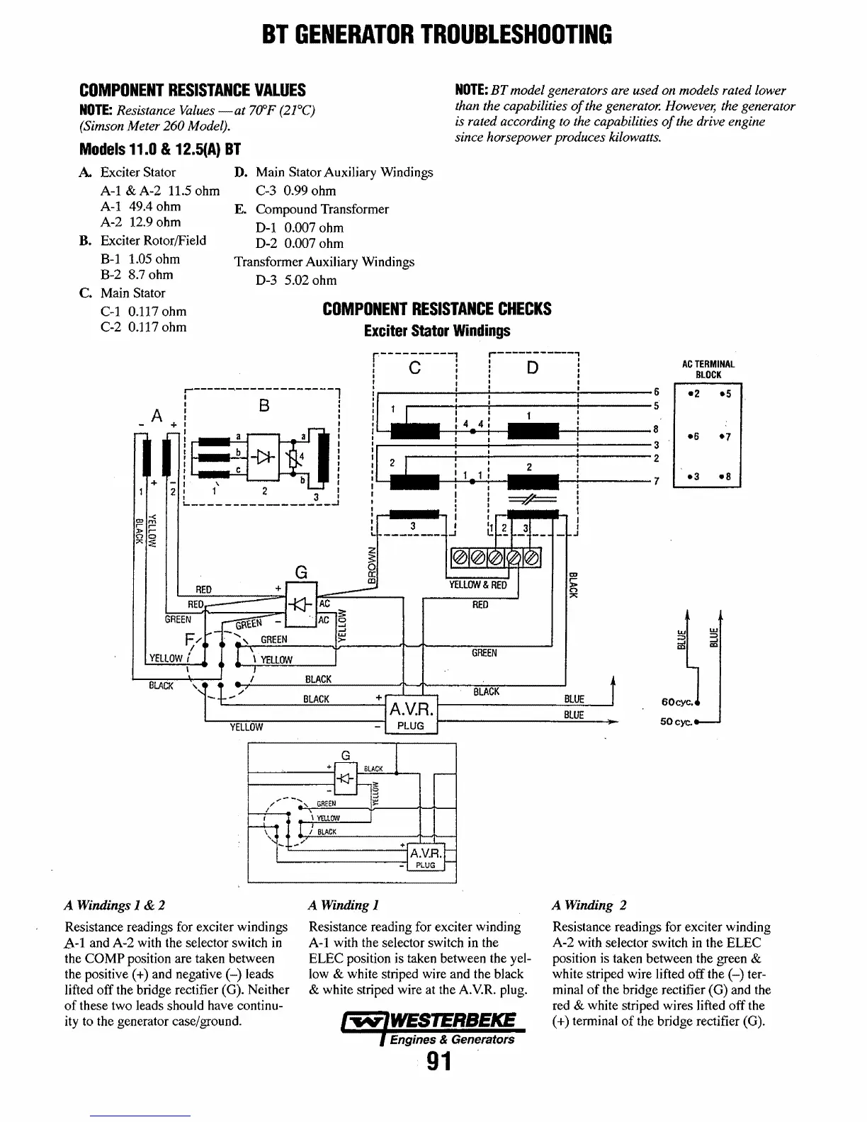
COMPONENT
RESISTANCE
CHECKS
Exciter
Stator
Windings
r-----~-------------l
AC
TERMINAL
BLOCK
6
-2
-5
5
: 8 !
A I I
+:
as(l!
II
:*
4 i
1
~~~11111~~--------
8
-6
-7
2
+
_:.
\
b:
2 : 1 2 3 I
~-----------------~
I
GREEN
F/
I
YElLOW
i
\
BLACK
....
A Windings 1 & 2
Resistance readings for exciter windings
A-I
and A-2 with the selector switch
in
the
COMP
position are taken between
the positive
(+)
and negative
(-)
leads
lifted off the bridge rectifier (G). Neither
of
these two leads should have continu-
ity to the generator case/ground.
lr-l··
3
·.,
1..---------
RED
GREEN
BLACK
BLACK
A Winding 1
Resistance reading for exciter winding
A-1
with the selector switch in the
ELEC position is taken between the
yel-
low & white striped wire and the black
& white striped wire at the A.V.R. plug.
Engines & Generators
91
3
2
7
-3
-8
BLUE
BLUE
50cyc.
A Winding 2
Resistance readings for exciter winding
A-2 with selector switch
in
the ELEC
position is taken between the green
&
white striped wire lifted off the
(-)
ter-
minal
of
the bridge rectifier (G) and the
red
& white striped wires lifted off the
(+)
terminal
of
the bridge rectifier (G).
 Loading...


