ALTERNATOR/REGULATOR
SERVICE
An
alterlUlte
method
for
removing the stator winding, brush
holder
regu/o.tor
unit
and
the
I.e.
diode rectifier assembly
from
the
rear bracket. With the front bracket and rotor
assembly separated from the rear half
of
the alternator:
1.
Insert a
flat~bladed
screwdriver between the stator core
and the edge
of
the rear bracket
on
the same side as the
brush-holder. Raise this side
of
the stator core away from
the bracket so as to open a gap
of
about 1/2 inch.
NOTE:
Be
careful
not
to allow the screwdriver blade to
enter far enough
to touch the stator winding.
2.
Maintaining the 1/2 inch gap, insert the screwdriver
between the stator core and the bracket on the rectifier
side and move the stator laterally toward the
brush· holder
for a distance
of
1/2 to 3/4
of
an
inch without lifting
it
from the bracket.
3. Insert a #2 Phillips screwdriver through this opening and
remove the two screws holding the rectifier.
4.
Remove the nut anchoring the B terminal bolt and the
capacitor mounted thereto on the outside rear
of
the
bracket. Then remove the third Phillips screw holding the
brush holder to
the bracket.
5. Carefully withdraw stator, brush holder and rectifier from
the rear bracket as one loosely connected unit.
With the bracket out
of
the way,
it
is
easy to unsolder the
stator winding leads from the rectifier quickly
to
avoid
heat damage to the diodes and
I.C
chips. It
is
also easier
to renew the brushes because there is
no
need
to
bend the
connecting plates between the brush holder and the
rectifier and possibly damage the rectifier.
When reversing this procedure, make sure that the stator
winding leads are gently pushed back (from possible contact
with the rotor body) after seating the stator into the rear
bracket.
INSPECTION
Diode
Diode troubles are classified as open-circuit and
short~c.ircuit.
When the diode is open-circuited, no current flows.
In
the
short-circuited diode,
curr_ent
flows
in
both directions.
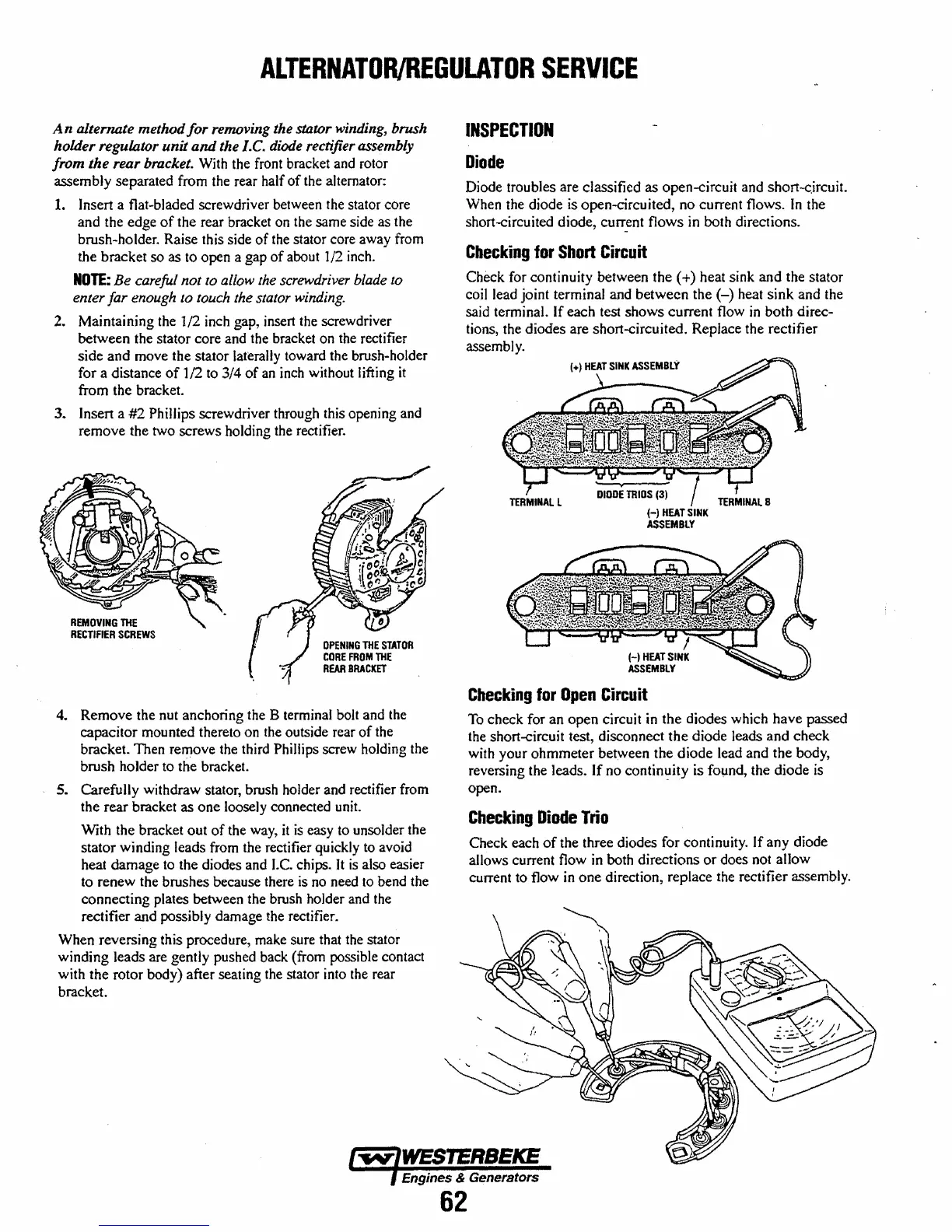
Checking
for
Short
Circuit
Check for continuity between the (+) heat sink and the stator
cojl lead joint terminal and betwecn the
(-)
heat sink and the
said
terminal. If each test shows current flow
in
both direc-
tions, the diodes are short-circuited. Replace the rectifier
assembly.
.
DIODE
TRIOS
(3)
HHEATSINK
ASSEMBLY
Checking
for
Open
Circuit
To
check for an open circuit
in
the diodes which have passed
the
short-circ.uit test, disconnect the diode leads and check
with your ohmmeter between the diode lead and the body,
reversing the leads.
If
no continllity is found, the diode
is
open.
Checking
Diode
Trio
Check each
of
the three diodes for continuity. If any diode
allows current flow in both directions
or
does not allow
current to flow
in
one direction, replace the rectifier assembly.
Engines & Generators
62
 Loading...


