en Installation
60 WILO SE 2019-07
▪The rated current set for the motor monitoring (menu 4.25–4.27)
6.5.6 Mains connection: Variable-speed
pump (electronically controlled
pumps)
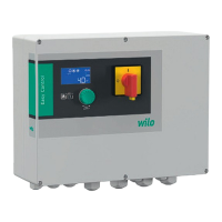
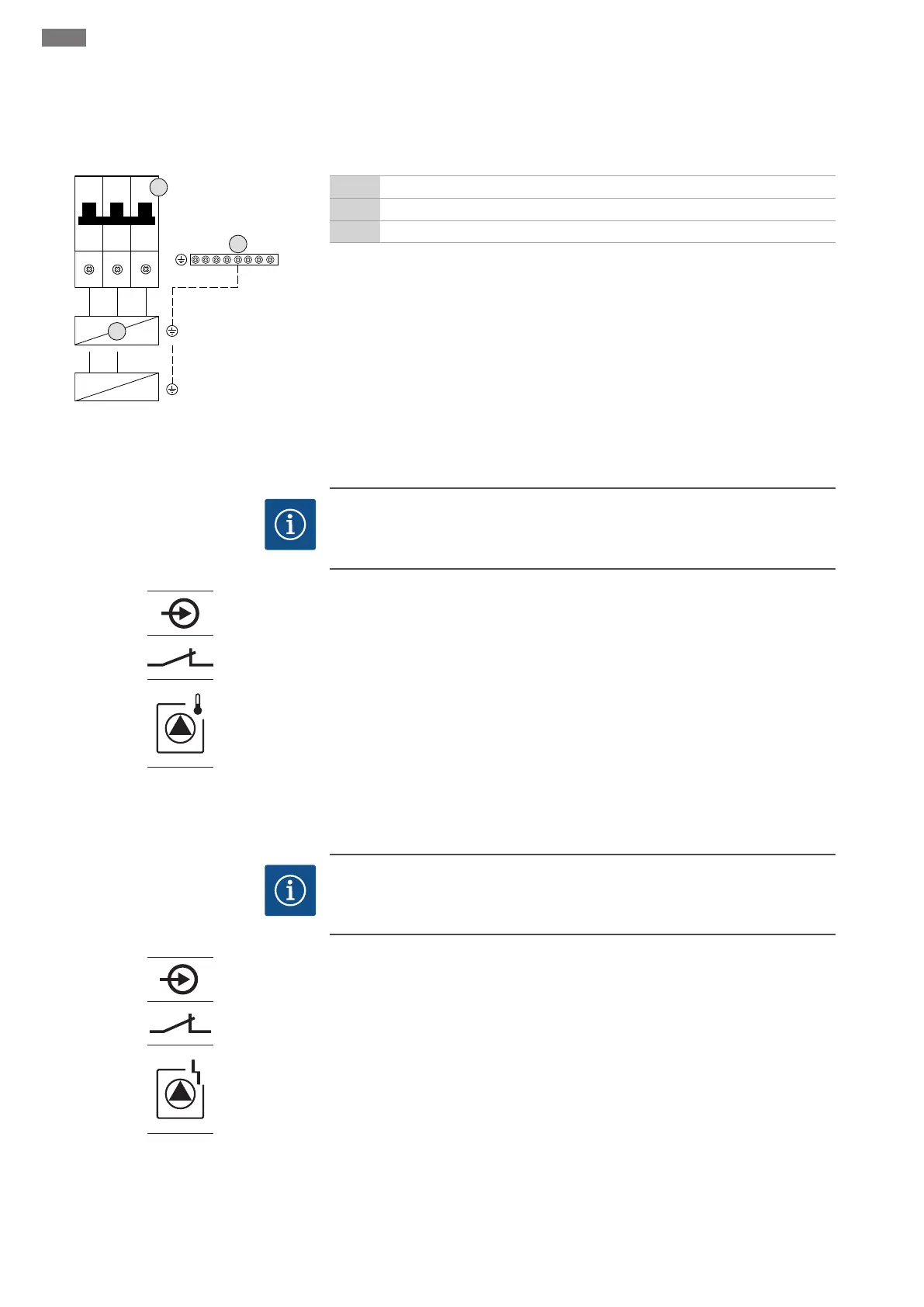
Fig.11: Pump connection
3 Terminal strip: Earth (PE)
5 Circuit breaker
FC Frequency converter
Insert the connection cable laid by the customer through the threaded cable glands and
secure. Connect the wires to the circuit breaker as per the connection diagram.
6.5.7 Connection, thermal motor mon-
itoring
NOTICE!Connection is only possible using the Wilo-Control EC-B switchgear!
NOTICE
Do not apply external voltage!
An external voltage which is applied destroys the component.
Fig.12: Connection overview symbol
One thermal motor monitoring device with bimetallic strips can be connected per
pump. Do not connect PTC or Pt100 sensors!
Insert the connection cable laid by the customer through the threaded cable glands and
secure. Connect the wires to the terminal strip according to the connection diagram.
Use the terminal number shown in the connection overview in the cover. The num-
ber shown in location “x” on the symbol indicates which pump it refers to:
▪1 = pump1
▪2 = pump2
▪3 = pump3
6.5.8 Connection to the frequency con-
verter error messages
NOTICE!Connection is only possible using the Wilo-Control ECe-B switchgear!
NOTICE
Do not apply external voltage!
An external voltage which is applied destroys the component.
Fig.13: Connection overview symbol
One external error message of the frequency converter can be connected per pump.
The frequency converter output needs to act as a normally closed contact!
Insert the connection cable laid by the customer through the threaded cable glands and
secure. Connect the wires to the terminal strip according to the connection diagram.
Use the terminal number shown in the connection overview in the cover. The num-
ber shown in location “x” on the symbol indicates which pump it refers to:
▪1 = pump1
▪2 = pump2
▪3 = pump3
 Loading...