INPUT
jOUTPUT
INSTRUCTIONS
The
I/o
instruction set
is
comprised of
eight
instructions,
as
listed below.
Instruction Name
Mnemonic
Start
Input/Output
SIO
Test
Input/Output
TIO
Test
Device
TDY
Halt
Input/Output
HIO
Reset
Input/Output
RIO
Poll
Processor POLP
Poll
and
Reset Processor
POLR
Acknowledge
Input/Output
Interrupt
AIO
OVERALL
CHARACTERISTICS
All
I/o
instructions
are
privi leged
and
can
be performed
only when
the
basic
processor
(BP)
is
in
either
the
master
or
master-protected
mode.
If
the
BP
attempts to
execute
an
I/o
instruction when
it
is
in the
slave
mode (bit 8
of
the
current
PSW
is
a 1),
the
instructi on
is
aborted
at
the
timl'> thl'>
nnl'>rntinn
c-nrll'>
is
rlpc-nrlprl
nnrl
thp
RP
trnns
to
10-
. - - - - - - - - 1- - -
--
- - - - - - - - - - - - - - I
cation
X1401. Programs
operating
in
the
slave
mode must
request
I/O
services from
the
System
Monitor.
At
the
end of
every
I/O
instruction,
the
condition
code
bits represent a summary descri pti on of
the
resu I ts of
the
I/O
operation
and conditions
within
the
addressed
I/O
subsystem.
Specific
condition
code
settings and meanings
(unique for
each
I/O
instruction)
are
contained
in
the
de-
tailed
description
for
each
I/O
instruction.
All
I/O
instructions,
except
RIO, may request
detailed
I/O
status information. The
type
and amount of
I/o
status
information
that
may be requested is determined by
the
op-
eration
code
and
the
R field of
the
I/O
instruction. The
R
field also
designates
which
general
register(s)
is
to be
loaded with
the
requested information. (Refer
to
I/o
Status
Informati on for further
detai
Is.
)
I/O
instructions
are
similar to other word-addressing
in-
structions in
that
bits 15-31 may be modified by
indirect
addressing
and/or
indexing.
However,
the
final
value
of
these bits is not used as
an
effective
virtual address for
memory
reference.
Instead,
depending
upon
the
I/o
in-
struction,
these bits
are
used
as
an
extension
to
the
opera-
tion
code
field,
as an
I/O
address
to
select
a
particular
I/o
subsystem, or
they
may be reserved. Further
detai
Is
of
I/o
instructions
are
illustrated
in Figure 13
and
de-
scribed in Table 13.
I/O
STATUS
INFORMATION
SIO,
TIO,
TDY,
AND
HIO INSTRUCTIONS
If
the
R
field
is
coded
with a
0,
no
status information
is
re-
quested
nor
loaded.
If
the R field
is
odd,
one
word of status
information
is
requested to
be
loaded into register R as
spec-
ified
by
the
R
field.
If
the
R field
is
even
(not
zero),
two
words
of
status information
are
requested to
be
loaded into
registers
Rand
Ru
1 .
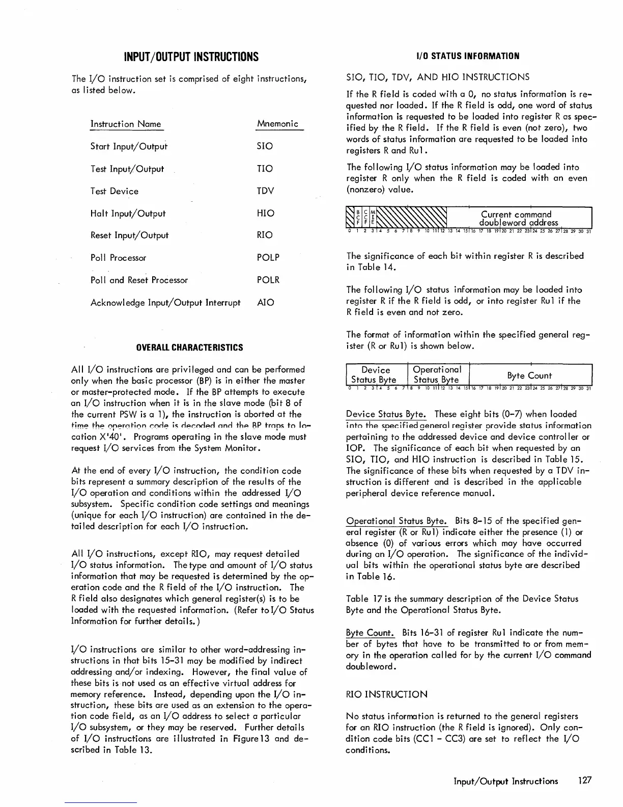
The
following
I/O
status information may be loaded
into
register
R only when
the
R
field
is
coded
with
an
even
(nonzero)
value.
The
significance
of
each
bit
within
register
R
is
described
in
Table 14.
The
following
I/O
status information may be loaded
into
register R if
the
R field is odd, or
into
register
Ru
1 if
the
R
fi
e I
dis
even
and
not
zero.
The format of information
within
the
specified
general
reg-
ister
(R
or
Ru1)
is shown below.
Device
Status Byte. These
eight
bits (0-7) when loaded
into
the
specified
general
register provide status information
pertaining
to
the
addressed
device
and
device
controller
or
lOP.
The
significance
of
each
bit
when requested by
an
SIO,
TIO,
and HIO instruction is described in Table
15.
The
significance
of
these
bits when requested by a
TDY
in-
struction
is
different
and
is
described
in
the
applicable
peripheral
device
reference
manual.
Operational
Status Byte. Bits
8-15
of
the
specified
gen-
eral register
(R
or
Ru1)
indicate
either
the
presence
(1)
or
absence
(0)
of various errors which may
have
occurred
during
an
I/O
operation.
The
significance
of
the
individ-
ual bits
within
the
operational
status
byte
are
described
in
Table
16.
Table 17 is
the
summary
description
of
the
Device
Status
Byte
and
the
Operational
Status Byte.
Byte
Count.
Bits 16-31 of register
Ru1
indicate
the
num-
ber
of
bytes
that
have to be transmitted to
or
from mem-
ory in
the
operation
called
for by
the
current
I/o
command
doubleword.
RIO INSTRUCTION
No
status information
is
returned to
the
general
registers
for
an
RIO
instruction (the R field is ignored).
Only
con-
dition
code
bits (CC 1 - CC3)
are
set to
reflect
the
I/O
conditions.
Input/Output
Instructions 127

 Loading...


