address if
PSWs
bit
9
is
zero
(no map), or a
20-bit
virtual
address if
PSWs
bit
9
is
one
(map). If
indirect
addressing is
specified,
the
indirect
word contains a
20-bit
address with
exactly
the same
properties.
Format 2
is
used
in
all
other
circumstances, namely:
1.
Bit
position
10
(AT)
contains a
one,
and
a.
The XPSD
is
not
being
executed
as
the
result
of
a
trap
or
interrupt,
or
b.
It
is
in a
trap
or
interrupt
location,
is
being
exe-
cuted
as
the result
of
a
trap
or
interrupt,
but
the
current
mode
of
the
PSWs
is
real-extended.
In
these
cases,
all
of the normal rules
of
address
calcu-
lations
hold,
i.e.,
indirect,
index,
and
map.
PSS
Address
Calculations.
PUSH
STATUS
(PSS)
address
cal-
culations
are
similar to
but
simpler than those for
the
XPSD
instruction.
Two
basic
formats
are
used:
Format 1:
Format 2:
Format 1
is
used when the
PSS
is
executed
in an
interrupt
or
trap
location
as a result of
an
interrupt
or
trap
sequence.
No indexing
is
possible
because
its
designator
field
is
pre-
empted
by
the
reference
address.
Indirect
addressing
is
per-
mitted with
the
same
constraint
against
indexing; the
indirect
address word
contains
a
20-bit
real address with
precisely
the same properties as the
reference
address.
In
the
case
of
a
trap
instruction, the
20-bit
reference
address
can
be
either
a
rea!
address
or
IJ
virtlJlJ! address IJccordil19
to
the
value
in
PSWs
bit
position
9.
Format 2
is
used when the
PSS
instruction
is
executed
in
the
course
of
normal program
execution.
Addressing in this
case
is
completely
standard, including indexing
and
indi-
rect
addressing.
During
the
execution
of
the
PSS
instruction the interrupt
stack
pointer
is
accessed
from real memory locations Oand
1.
The
interrupt
stack
address
therein
is
a real
20-bit
address
with no
indexing
or
mapping
used.
''''V~T\A/,
tilTH,
and
f\.~TB
Address
Ca!cu!ations.
T'vvc
bas:c
formats
are
used in modify
and
test instructions:
Format 1:
26 Main Memory
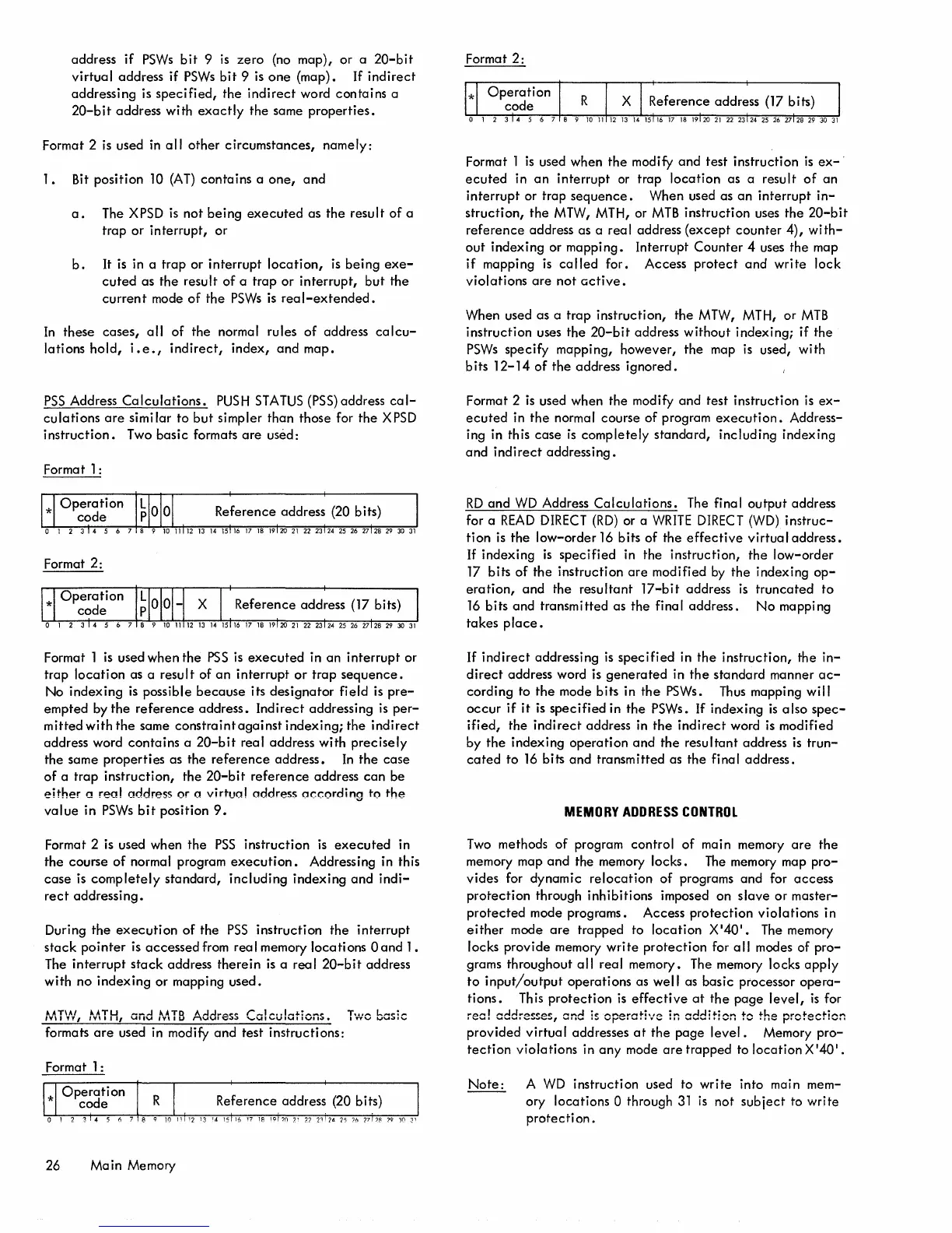
Format
2:
Format 1
is
used when
the
modify
and
test
instruction
is
ex-'
ecuted
in
an
interrupt
or trap
location
as a result
of
an
interrupt
or trap
sequence.
When used as
an
interrupt
in-
struction,
the
MTW, MTH, or
MTB
instruction uses
the
20-bit
reference
address as a
rea
I address
(except
counter
4),
with-
out
indexing or mapping. Interrupt
Counter
4 uses the map
if
mapping
is
called
for. Access
protect
and
write
lock
violations
are
not
active.
When used as a
trap
instruction,
the
MTW, MTH, or
MTB
instruction uses
the
20-bit
address
without
indexing;
if
the
PSWs
specify mapping, however,
the
map
is
used, with
bits
12-14
of
the
address
ignored.
Format 2
is
used when the modify
and
test instruction
is
ex-
ecuted
in
the
normal course of program
execution.
Address-
ing in this
case
is
completely
standard, including indexing
and
indirect
addressing.
RD
and
WD
Address
Calculations.
The final
output
address
for a
READ
DIRECT
(RD)
or a
WRITE
DIRECT
(WD)
instruc-
tion
is
the
low-order
16
bits of the
effective
virtual
address.
If
indexing
is
specified
in the instruction,
the
low-order
17
bits
of
the
instruction
are
modified
by
the indexing
op-
eration,
and
the
resultant
17-bit
address
is
truncated
to
16
bits and transmitted as the final address.
No
mapping
takes
place.
If
indirect
addressing
is
specified
in
the
instruction,
the
in-
direct
address word
is
generated
in
the
standard manner
ac-
cording to
the
mode bits in
the
PSWs.
Thus
mapping will
occur
if
it
is
specified
in
the
PSWs. If indexing
is
also
spec-
ified,
the
indirect
address in
the
indirect
word
is
modified
by
the
indexing
operation
and
the
resultant address
is
trun-
cated
to
16
bits
and
transmitted as
the
final address.
MEMORY
ADDRESS
CONTROL
Two
methods of program control
of
main memory
are
the
memory map
and
the memory locks.
The
memory map
pro-
vides for dynamic
relocation
of
programs and for
access
protection
through inhibitions imposed on
slave
or
master-
protected
mode programs. Access
protection
violations in
either
mode
are
trapped to
location
X'40'.
The memory
locks provide memory
write
protection
for
all
modes of
pro-
grams throughout
all
real memory. The memory locks
apply
to
input/output
operations as
well
as basic processor
opera-
tions.
Th
is
protection
is
effective
at
the
page
level,
is
for
reef addresses, and
is
cperati'w'c in
addition
to the
protection
provided
virtual
addresses
at
the
page
level.
Memory
pro-
tection
violations in
any
mode
are
trapped to
location
X'40'.
Note:
A
WD
instruction used to
write
into main mem-
ory locations
0 through
31
is
not
subject
to
write
protecti
on.

 Loading...


