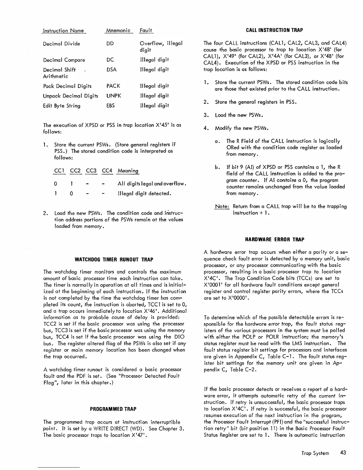
Instruction
Name
Mnemonic
Fault
Decimal Divide
DD
Overflow,
i lIega I
digit
Decimal Compare
DC
Illegal
digit
Decimal Shift
DSA
Illegal
digit
Arithmetic
Pack Decimal Digits
PACK
Illegal
digit
Unpack Decimal Digits UNPK
Illegal
digit
Edit Byte String
EBS
Illegal
digit
The
execution
of
XPSD or
PSS
in
trap
location
X
'
45
1
is as
follows:
1 • Store
the
current
PSWs. (Store
genera
I registers
if
PSS.) The
stored
condition
code
is
interpreted
as
follows:
CC 1
CC2 CC3
CC4
Meaning
o All
digits
legal
and
overflow.
o
Illegal
digit
detected.
2.
Load
the
new PSWs. The
condition
code
and
instruc-
tion
address portions
of
the
PSWs
remain
at
the
values
loaded from memory.
WATCHDOG
TIMER
RUNOUT
TRAP
The
watchdog
timer monitors
and
controls
the
maximum
amount
of
basic
processor time
each
instruction
can
take.
The timer
is
normally in
operation
at
all
times
and
is
initial-
ized
at
the
beginning
of
each
instruction.
If
the
instruction
is
not
completed
by
the
time the
watchdog
timer has
com-
pleted
its
count,
the
instruction
is
aborted,
TCC
1
is
set
to
0,
and
a trap
occurs
immediately
to
location
X
'
46
I
•
Additional
information as to
probable
cause
of
delay
is
provided:
TCC2
is
set
if the
basic
processor was using
the
processor
bus,
TCC3 is
set
if
the
basic processor was using
the
memory
bus,
TCC4
is
set
if
the
basic
processor was using
the
DIO
bus. The
register
altered
flag
of
the
PSWs
is
also
set
if
any
register or main memory
location
has
been
changed
when
the trap
occurred.
A
watchdog
timer runout
is
considered a
basic
processor
fault
and
the
PDF
is
set.
(See
"Processor
Detected
Fault
Flag",
later
in this
chapter.)
PROGRAMMED
TRAP
The programmed trap occurs
at
instruction
interruptible
point.
It
is
set
by a
WRITE
DIRECT
(WD). See
Chapter
3.
The basic processor traps to
location
X 147'.
CALL
INSTRUCTION
TRAP
The four
CALL
instructions
(CAll,
CAL2, CAL3,
and
CAL4)
cause
the
basic
processor
to
trap
to
location
X
'
48
1
(for
CAll),
X
'
49
1
(for CAL2), X
'
4A'
(for CAL3),
or
X
'
4B
'
(for
CAL4). Execution
of
the
XPSD
or
PSS
instruction
in
the
trap
location
is
as
follows:
1.
Store
the
current
PSWs. The stored
condition
code
bits
are
those
that
existed
prior
to
the
CA
LL
instruction.
2.
Store
the
general
registers in PSS.
3.
Load
the
new PSWs.
4.
Modify
the
new PSWs.
a.
The R Field
of
the
CALL
instruction
is
logically
ORed with
the
condition
code
register
as
loaded
from memory.
b.
If
bit
9 (AI)
of
X
PSD
or
PSS
contains
a 1,
the
R
field
of
the
CALL
instruction
is
added
to
the
pro-
gram
counter.
If AI
contains
a
0,
the
program
counter
remains
unchanged
from
the
value
loaded
from memory.
Note:
Return from a CALL
trap
wi"
be
to
the
trapping
instruction
+ 1 •
HARDWARE
ERROR
TRAP
A
hardware
error
trap
occurs when
either
a
parity
or
a
se-
quence
check
fault
error
is
detected
by a memory
unit,
basic
processor,
or
any
processor communicating
with
the
basic
processor, resulting in a
basic
processor trap
to
location
X
'
4C.
The Trap
Condition
Code
bits (TCCs)
are
set
to
X'0001
'
for
all
hardware
fault
conditions
except
general
register
and
control
register
parity
errors,
where
the
TCCs
are
set
to
X 10000 1 .
To
determine
which
of
the
possible
detectable
errors
is
re-
sponsible for
the
hardware
error
trap,
the
fault
status
reg-
isters
of
the various processors in the system must
be
polled
with
either
the
POLP
or
POLR
instruction;
the
memory's
status
register
must
be
read
with
the
LMS
instruction.
The
fault
status
register
bit
settings
for processors
and
interfaces
are
given
in Appendix
C,
Table
C-1.
The
fault
status
reg-
ister
bit
settings
for
the
memory
unit
are
given
in
Ap-
pendix
C,
Table
C-2.
If
the
basic processor
detects
or
receives
a report of a
hard-
ware
error,
it
attempts
automatic
retry of
the
current
in-
struction.
If retry
is
unsuccessful,
the
basic
processor traps
to
location
X
'4C.
If retry
is
successful,
the
basic
processor
resumes
execution
of
the
next
instruction in
the
program,
the
Processor
Fault
Interrupt (PFI)
and
the
"successful
instruc-
tion retryll
bit
(bit
position 11) in
the
Basic Processor
Fault
Status Register
are
set
to
1.
There
is
automatic
instruction
Trap System
43

 Loading...


