Table
19.
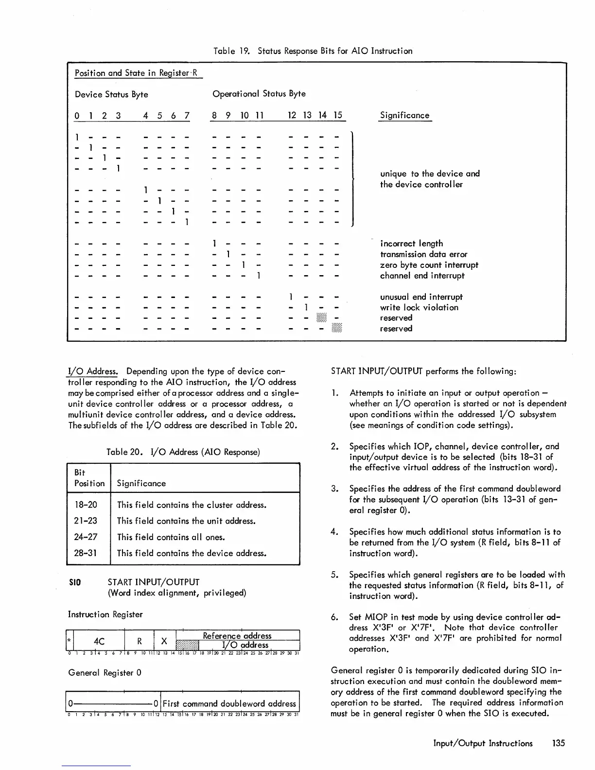
Status Response Bits for AIO Instruction
Position and
State
in Register-R
Device Status Byte
Operational
Status Byte
o
2 3
4
567
8 9
10
11
12
13
14 15
Significance
I/O
Address. Depending upon
the
type of
device
con-
troller responding
to
the
AIO instruction,
the
I/O
address
may be comprised
either
of a processor address and a
single-
unit
device
controller address or a processor address, a
multiunit
device
controller address, and a
device
address.
The
subfields of
the
I/O
address
are
described in Table 20.
Table 20.
I/o
Address (AIO Response)
Bit
Position
Significance
18-20 This field contains the cluster address.
21-23
This
field
contains
the
unit address.
24-27
This field contains all ones.
28-31 This field contains
the
device
address.
SID
START
INPUT/OUTPUT
(Word index alignment, privileged)
Instruction Register
General
Register 0
unique to
the
device
and
the
device
controller
incorrect length
transmission
data
error
zero
byte
count
interrupt
channel end interrupt
unusual end interrupt
write
lock
violation
reserved
reserved
START
INPUT/OUTPUT performs
the
following:
1.
Attempts
to
initiate
an
input or output
operation-
whether an
I/O
operation is started or not
is
dependent
upon conditions within
the
addressed
I/o
subsystem
(see meanings of
condition
code
settings).
2. Specifies which
lOP,
channel,
device
controller,
and
input/output
device
is to be
selected
(bits 18-31 of
the
effective
virtual address of
the
instruction word).
3. Specifies the address of
the
first command doubleword
for
the
subsequent
I/O
operation (bits 13-31 of
gen-
eral register 0).
4.
Specifies how much additional status information is
to
be returned from
the
I/O
system
(R
field,
bits 8-11 of
instruction word).
5.
Specifies which general registers
are
to
be loaded with
the
requested status information
(R
field,
bits
8-11,
of
instruction word).
6. Set MIOP in test mode by using
device
controller
ad-
dress
X'3P
or X'7F'.
Note
that
device
controller
addresses X'3F' and X'7F' are prohibited for normal
operation.
General
register 0 is temporari
Iy
dedicated
during SIO
in-
struction
execution
and must
contain
the
doubleword mem-
ory address of
the
first command doubleword specifying
the
operation
to
be started.
The
required address information
must be in general register 0 when
the
SIO
is
executed.
Input/Output
Instructions
135

 Loading...


