Status information for
an
S10
instruction isalways returned
via
condition
code
bits. Additional information may be
requested and returned via
the
general registers as
speci-
fied by
the
R field of
the
S10
instruction. However,
the
return of
the
additional information is
dependent
upon
conditions
encountered within
the
addressed
I/O
subsystem
(see meanings of
condition
code
settings).
If
the
R
field
is coded with a 0, no additional status
in-
formation is requested.
If
the
R field is coded with
an
odd
value,
one word of
status information is requested
to
be loaded into register
R.
The format of this information is
as
follows:
If
the
R
field
is coded with
an
even
(nonzero)
value,
two
words of status information
are
requested. The format of
information within register
Ru1
is as shown
above.
The
format of information within register R is as
follows:
These responses provide
the
program with information
nec-
essary
to
determine
the
current status of
the
addressed
I/o
subsystem. The byte
count
field
indicates
the number of
bytes
that
are
to
be transmitted
to
or from memory in
the
operation
called
for
by
the
current command doubleword.
The other fields
are
described in Tables 14-17.
Affected: (R), (Ru1), CC
The meaning of
the
condition
code
bits during an SIO
in-
struction is:
2 3 4 Meaning
o 0 0 0
I/O
address
recognized,
S10
accepted,
and
status information in general registers
is
corre~t.
o 0
o For
RMP,
I/O
address recognized and
S10
accepted;
however, status i nformati on in
general registers may be incorrect. For
MIOP, not possible.
o 0 0
I/O
address
recognized,
SIO
not
accepted
o
o
because
device
controller
or
device
is busy,
and status information in general registers is
correct.
o For
RMP,
I/O
address
recognized,
SIO not
accepted
because
device
controller
or
device
is busy, and status information in general
registers may be incorrect. For MIOP, not
possible.
o Processor
Interface
detected
parity error
on
returned status
and/or
condition
code.
The
result of
the
SIO is indeterminate.
136
Input/Output
Instructions
2 3 4 Meaning
o 0
I/o
address not
recognized,
SIO not
ac-
cepted,
and status information returned to
general registers is incorrect.
o
No
I/O
address recognized and SIO aborted
because
an
error
detected
when
the
lOP
at-
tempted
to
read and transfer
the
_S10
param-
eters
(device/device
controller address, R
field information, and first command
double-
word address)
from
the
BP
to the
lOP
via main
memory. Status information returned to
gen-
eral registers
is
incorrect.
If
CC4 = 1,
the
MIOP is in test mode and
the
meaning of
the
condition
code
during
an
SIO is:
2 3 4 Meaning
o 0 Set test mode is successful.
o Set test mode is successful, but a
Bus
Check
Fault was
detected.
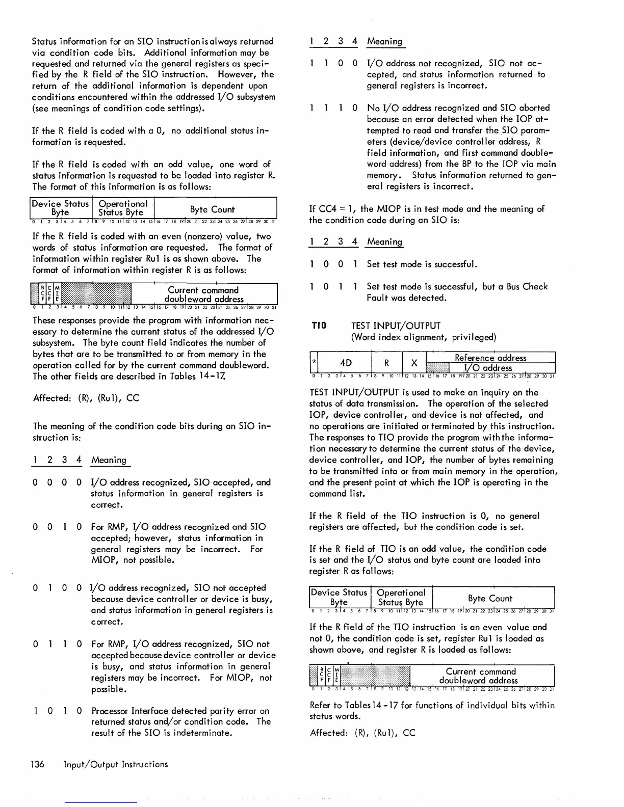
TID
TEST
INPUT/OUTPUT
(Word index alignment, privileged)
TEST
INPUT/OUTPUT is used
to
make
an
inquiry
on
the
status of
data
transmission. The operation of
the
selected
lOP,
device
controller,
and
device
is not
affected,
and
no operations
are
initiated
or terminated by this instruction.
The responses
to
no
provide the program with
the
informa-
tion necessary to determine
the
current status of the
device,
device
controller,
and
lOP,
the
number of bytes remaining
to
be transmitted into or from main memory in the
operation,
and
the
present point
at
which
the
lOP
is operating in
the
command list.
If
the
R field of
the
no
instruction is 0, no general
registers
are
affected,
but
the
condition
code
is set.
If
the
R field of
no
is an odd
value,
the condition
code
is set and
the
I/o
status and byte
count
are
loaded into
register R
as
follows:
If
the
R field of
the
no
instruction is
an
even
value
and
not 0,
the
condition
code
is set, register
Ru1
is loaded as
shown
above,
and register R is loaded as follows:
Refer to Tables 14
-17
for functions of individual bits within
status words.
Affected:
(R),
(Ru1), CC

 Loading...


