initial
value
plus
the
initial
value
word count
and
the
value
of
the
9-
or
10-bit
control
start
field
is
equal to its
initial
value
plus 4 times
the
initial
word
count.
The memory write
loc~
registers
are
treated
as
a
circular
set,
with
the
register for memory addresses
X'O'-X'lFF'
(first
page)
immediately
following
the
register
for memory
ad-
dresses X'FFEOO'-X'FFFFF' (last
page).
Overwriting
the
first registers
occurs
when
2-bit
write
lock images
are
being
processed
and
the
word
count
is
greater
than
128.
INTERRUPTION
-OF
MMC
The
execution
of
MMC
can
be
interrupted
after
each
word
of
the
control image has
been
moved into
the
specified
con-
trol
register.
Immediately prior
to
the
time
that
the
instruc-
tion
in
the
interrupt
ortrap
location
is
executed,
the
instruc-
tion
address portion
of
the program status words
contains
the
virtual
address
of
the
MMC
instruction,
register
R
contains
the
virtual
address
of
the
next
word
of
the
control image to
be
locided,
and
register
Ru
1
contains
a
count
of
the
number
of
control image words remaining to be moved
and
a
value
pointing
to
the
next
memory control
register
to
be
loaded.
After
interrupt,
the
MMC instruction may be resumed from
the
point
it
was
interrupted.
MEMORY
ACCESS
TRAPS
BY
MMC
INSTRUCTION
A
trap
during
execution
of
the
MMC instruction
can
occur
if
the
pages
containing
the
control images
are
nonexistent
or
are
protected
in
the
master-protected
mode. The
regis-
ters
Rand
Ru
1 may be a I
tered
for
the
above
case.
If
a
parity
error should
occur
during
access
of a control image
word,
theMMC
instruction will
trap
with
the
RegisterAItered
indicator
set
indicating
that
a
change
has been made to
the
memory control registers. The registers
Rand
Ru
1 will be
restored
to
their
initial
values,
prior
to
the
point
at
which
the
trap
occurred.
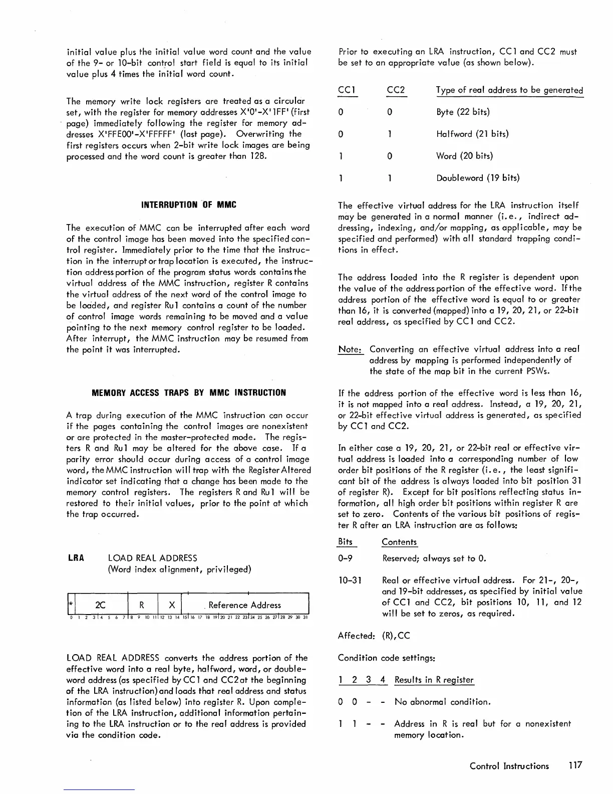
LRA
LOAD
REAL
ADDRESS
(Word index al
ignment,
privileged)
LOAD
REAL
ADDRESS
converts
the
address portion
of
the
effective
word
into
a reaf
byte,
halfword,
word,
or
double-
word address (as
specified
by CC 1
and
CC2
at
the
beg inn ing
of
the
LRA
instruction)
and
loads
that
real
address
and
status
information (as
listed
below) into
register
R.
Upon
comple-
tion
of
the
LRA
instruction,
additional
information
pertain-
ing
to
the
LRA
instruction
or
to
the
real
address
is
provided
via
the
condition
code.
Prior to
executing
an
LRA
instruction,
CC 1
and
CC2
must
be
set to
an
appropriate
value
(as shown below).
CCl
CC2
Type
of
real address
to
be
generated
0 0
Byte (22 bits)
0
Halfword
(21
bits)
0
Word (20 bits)
Doubleword (19 bits)
The
effective
virtual
address for
the
LRA
instruction
itself
may
be
generated
in a normal manner
(i.
e.,
indirect
ad-
dressing,
indexing,
and/or
mapping,
as
applicable,
may
be
specified
and
performed) with
all
standard
trapping
condi-
tions
in
effect.
The address
loaded
into
the
R
register
is
dependent
upon
the
value
of
the
address portion
of
the
effective
word.
If
the
address portion
of
the
effective
word is
equal
to
or
greater
than
16, it
is
converted
(mapped) into a 19,
20,
21,
or
22-bit
real
address,
as
specified
by
CC 1 and
CC2.
Note:
Converting
an
effective
virtual address into a
real
address by mapping
is
performed
independently
of
the
state
of
the
map
bit
in
the
current
PSWs.
If
the
address portion
of
the
effective
word is less
than
16,
it
is
not mapped into a
real
address.
Instead,
a 19,
20,
21,
or 22-bit
effective
virtual
address is
generated,
as
specified
by CC 1
and
CC2.
In
either
case a 19,
20,
21,
or
22-bit
real or
effective
vir-
tual address is
loaded
into a corresponding number
of
low
order
bit
positions
of
the
R
register
(i.
e.,
the
least
signifi-
cant
bit
of
the
address
is
always loaded
into
bit
position 31
of
register
R).
Except for
bit
positions
reflecting
status
in-
formation,
all
high
order
bit
positions
within
register
Rare
set
to
zero.
Contents
of
the
various
bit
positions
of
regis-
ter
R
after
an
LRA
instruction
are
as follows:
Bits
0-9
10-31
Contents
Reserved;
always
set
to
O.
Real
or
effective
virtual
address. For
21-,
20-,
and
19-bit
addresses,
as
specified
by
initial
value
of
CC 1
and
CC2,
bit
positions 10, 11,
and
12
will be
set
to
zeros,
as
required.
Affected:
(R),CC
Condition
code
settings:
2 3 4 Results
in
R
register
o 0
No
abnormal
condition.
- Address in R is
real
but for a
nonexistent
memory
location.
Control Instructions
117

 Loading...


