Normally,
bit
positions 15-31 may be ignored insofar as the
operation
of
the
MMC instruction is
concerned.
The results
of
the
instruction
are
the
same
whether
MMC
is
indirectly
or
directly
addressed.
However,if
MMC
is
indirectly
ad-
dressed
and
the
indirect
reference
address
is
nonexistent,
the
nona
II
owed
operation
trap
(location
X
'
40
'
)
is
activated.
The R
field,
which must be coded with
an
even
value,
des-
ignates
an
even-odd
pair
of
general
registers
(R
and
Ru1)
that
contain
additional
control information required by
the
MMC
instruction.
If
the
R fi eld
is
coded with an odd va I ue
a
trap
to
location
X
'
4D
'
(instruction
exception
trap)
occurs.
Depending upon
the
type
of
addressing,
the
contents of
register
R may be as follows:
If
MA
=
0,
contents
of
register
Rare:
If
MA
= 1
and
MM
=
0,
the
contents
of
register
Rare:
In
either
case,
the
Control Image Address
is
the
virtual
ad-
dress
of
a control word within
the
control image
area
to be
loaded
into a
block
of memory control
registers,
as
specified
by
the
contents
of
register
Ru
1.
Depending upon
the
type
of
control image
being
loaded,
the
contents
of
register
Ru
1 may
be
in
one
of
the
following
three
formats:
For loading memory map image
(either
a-bit
or
11-bit
for-
mat),
contents
of
register
Ru
1
are:
For loading
4-bit
write lock images,
contents
of
register
Ru1
are:
For loading
access
protection
or
2-bit
write lock images,
contents
of
register
Ru
1
are:
The
Count
field
(bit positions
0-7)
specifies
the
numberof
words
to
be
loaded
from the control image
area.
If
the
initial
word
count
is
zero,
a word count of 256
is
implied.
114 Controi Instructions
The Control Start field (bit positions
15-20,
21, or 22)
points to
the
beginning
of
the memory region
controlled
by
the
registers to be
loaded.
The
significance
of this field
is
different
for the 5 modes of MMC
operations
and
is
des-
cribed
within
each
mode below.
Affected:
(R),(Ru1),
memory control
storage
T raps: Instruction
exception,
nonallowed
operation.
LOADING
THE
MEMORY
MAP
CONTROL IMAGE
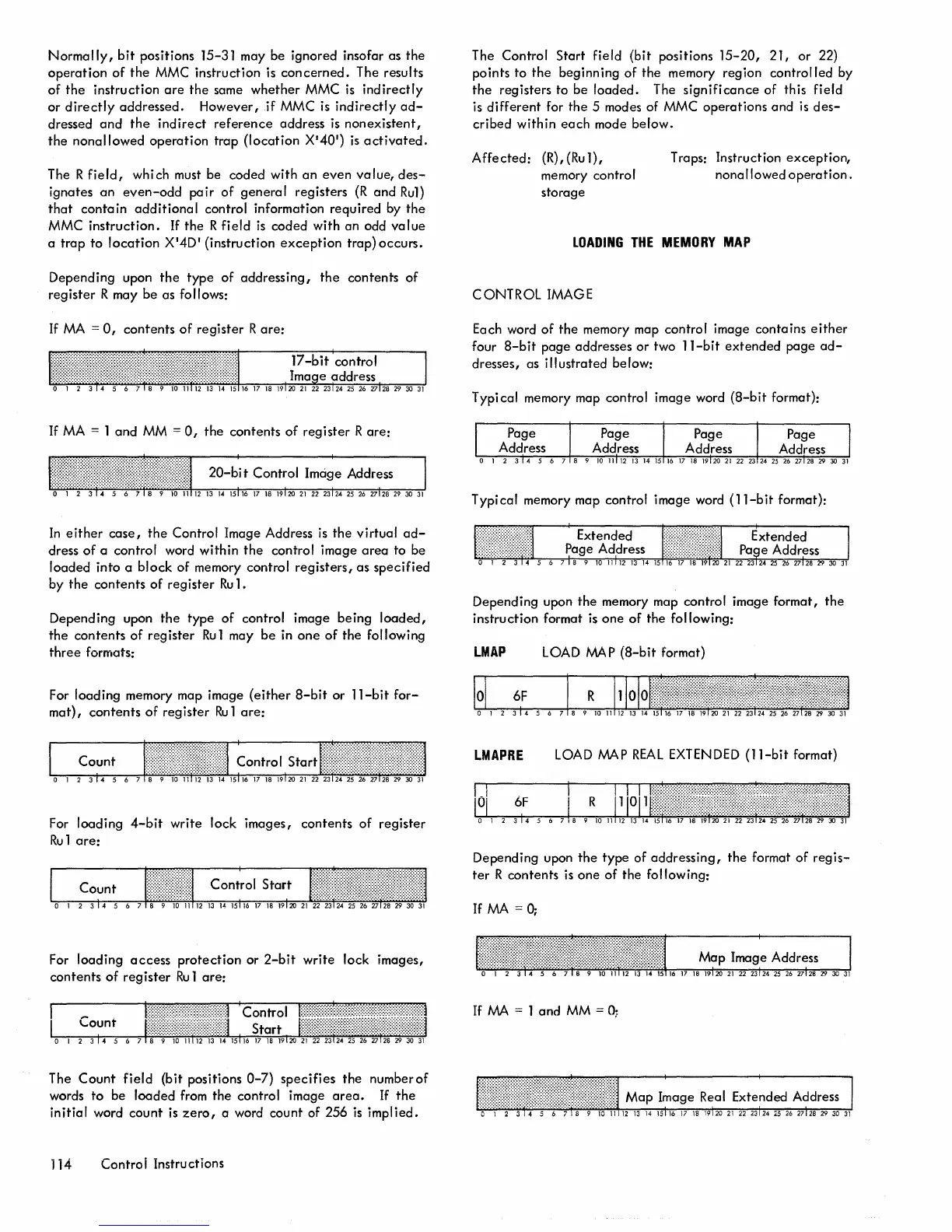
Each word
of
the
memory map control image contains
either
four
a-bit
page addresses
or
two
ll-bit
extended
page
ad-
dresses, as illustrated below:
Typical memory map control image word
(a-bit
format):
Typical memory map control image word
(ll-bit
format):
Depending upon
the
memory map control image format,
the
instruction format
is
one
of
the following:
LMAP
LOAD
MAP
(a-bit
format)
LMAPRE
LOAD
MAP
REAL
EXTENDED
(ll-bit
format)
Depending upon
the
type of
addressing,
the
format
of
regis-
ter
R contents
is
one
of
the following:
If
MA
=
0;
Map
lma~e
Address
I
If
MA
= 1
and
MM
=
0;

 Loading...


