INFORMATION
BOUNDARIES
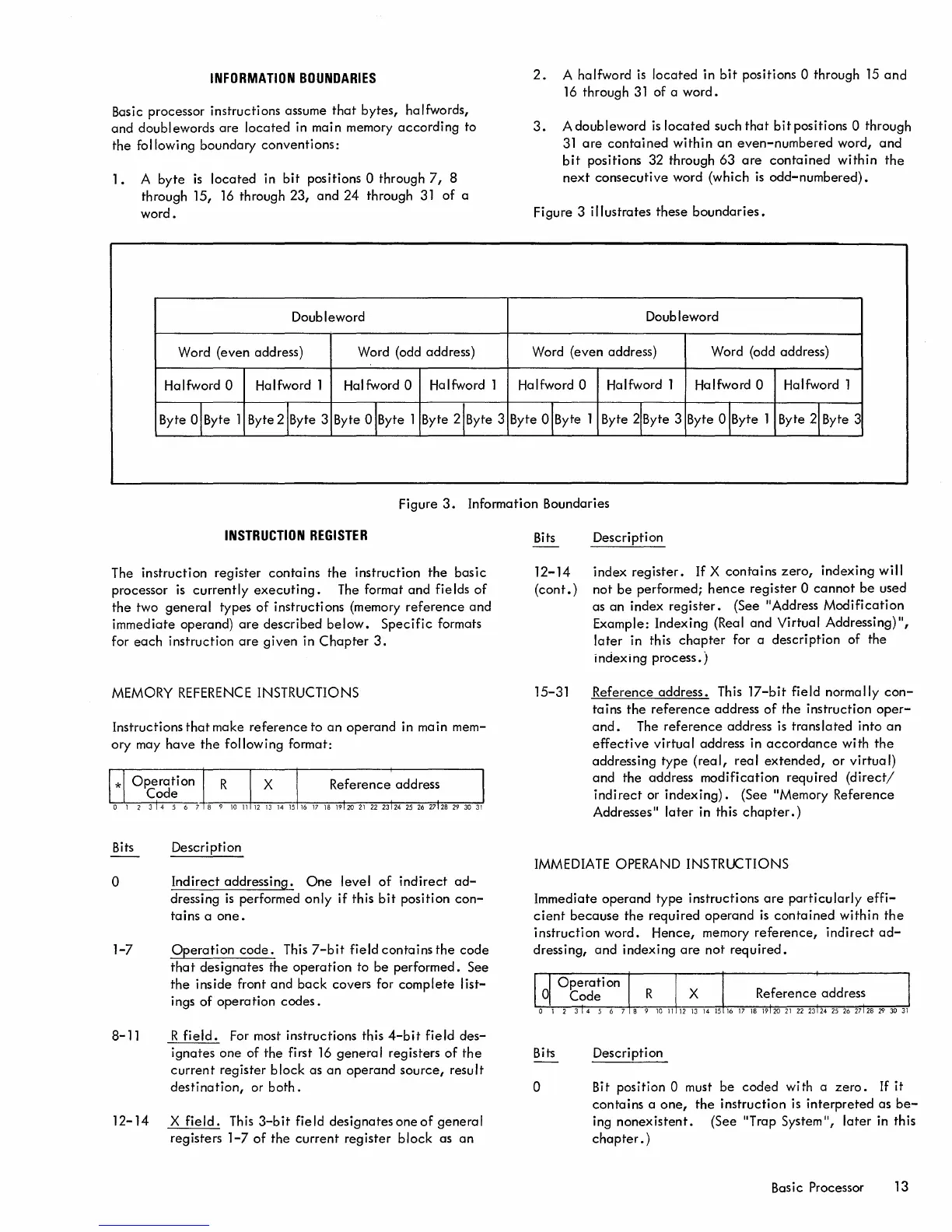
Basic processor instructions assume
that
bytes,
halfwords,
and doublewords
are
located
in main memory
according
to
the following boundary
conventions:
1.
A
byte
is
located
in
bit
positions 0 through
7,
8
through 15,
16
through 23,
and
24
through
31
of
a
word.
Doubleword
Word (even address)
Word (odd address)
Halfword
0 Halfword 1 Halfword 0
Halfword 1
Byte
O!
Byte 1
Byte 2!Byte 3
Byte 0 !Byte 1
Byte 2!Byte 3
2.
A halfword
is
located
in
bit
positions 0 through
15
and
16
through
31
of
a
word.
3.
A doubleword
is
located
such
that
bit
positions 0 through
31
are
contained
within
an
even-numbered
word,
and
bit
positions 32 through
63
are
contained
within
the
next
consecutive
word (which
is
odd-numbered).
Figure 3
illustrates
these
boundaries.
Doubleword
Word (even address)
Word (odd address)
Halfword
0
Halfword 1 Halfword 0 Halfword 1
Byte
O!
Byte 1 Byte 2!Byte 3 Byte 0 !Byte 1 Byte 2!Byte 3
Figure
3.
Information Boundaries
INSTRUCTION
REGISTER
The instruction
register
contains
the
instruction
the
basic
processor
is
currently
executing.
The format
and
fields
of
the
two
general
types
of
instructions (memory
reference
and
immediate operand)
are
described
below.
Specific
formats
for
each
instruction
are
given
in
Chapter
3.
MEMORY
REFERENCE
INSTRUCTIONS
Instructions
that
make
reference
to
an
operand
in main mem-
ory may
have
the
following format:
Bits
Description
o
1-7
Indirect
addressing.
One
level
of
indirect
ad-
dressing
is
performed
only
if
this
bit
position
con-
tains a
one.
Operation
code.
This
7-bit
field
contains
the
code
that
designates
the
operation
to
be
performed. See
the
inside front
and
back
covers for
complete
list-
ings
of
operation
codes.
8-11 R
field.
For most instructions this
4-bit
field
des-
ignates
one
of
the
first
16
general
registers
of
the
current
register
block
as
an
operand
source,
result
destination,
or
both.
12-14
X
field.
This
3-bit
field
designates
one
of
general
registers
1-7
of
the
current
register
block
as
an
Bits Description
12-14
index
register.
If
X
contains
zero,
indexing
will
(cont.)
not
be
performed;
hence
register
0
cannot
be
used
as
an
index
register.
(See "Address
Modification
Example: Indexing (Real and Virtual Addressing)
",
later
in this
chapter
for a
description
of
the
indexing
process.)
15-31 Reference
address.
Th
i s 17
-b
i t
fi
e I d norma
II
y
con-
tains
the
reference
address
of
the
instruction
oper-
and.
The
reference
address
is
translated
into
an
effective
virtual
address in
accordance
with
the
addressing
type
(real,
real
extended,
or
virtual)
and
the address
modification
required
(direct!
indirect
or
indexing).
(See "Memory Reference
Addresses"
later
in this
chapter.)
IMMEDIATE OPERAND INSTRUCTIONS
Immediate
operand
type instructions
are
particularly
effi-
cient
because
the
required
operand
is
contained
within
the
instruction
word.
Hence,
memory
reference,
indirect
ad-
dressing,
and
indexing
are
not
required.
Bits
o
Description
Bit position
0 must
be
coded
with a
zero.
If
it
contains
a
one,
the
instruction
is
interpreted
as
be-
ing
nonexistent.
(See "Trap System ",
later
in this
chapter.
)
Bas
i c Processor 13

 Loading...


