Bit
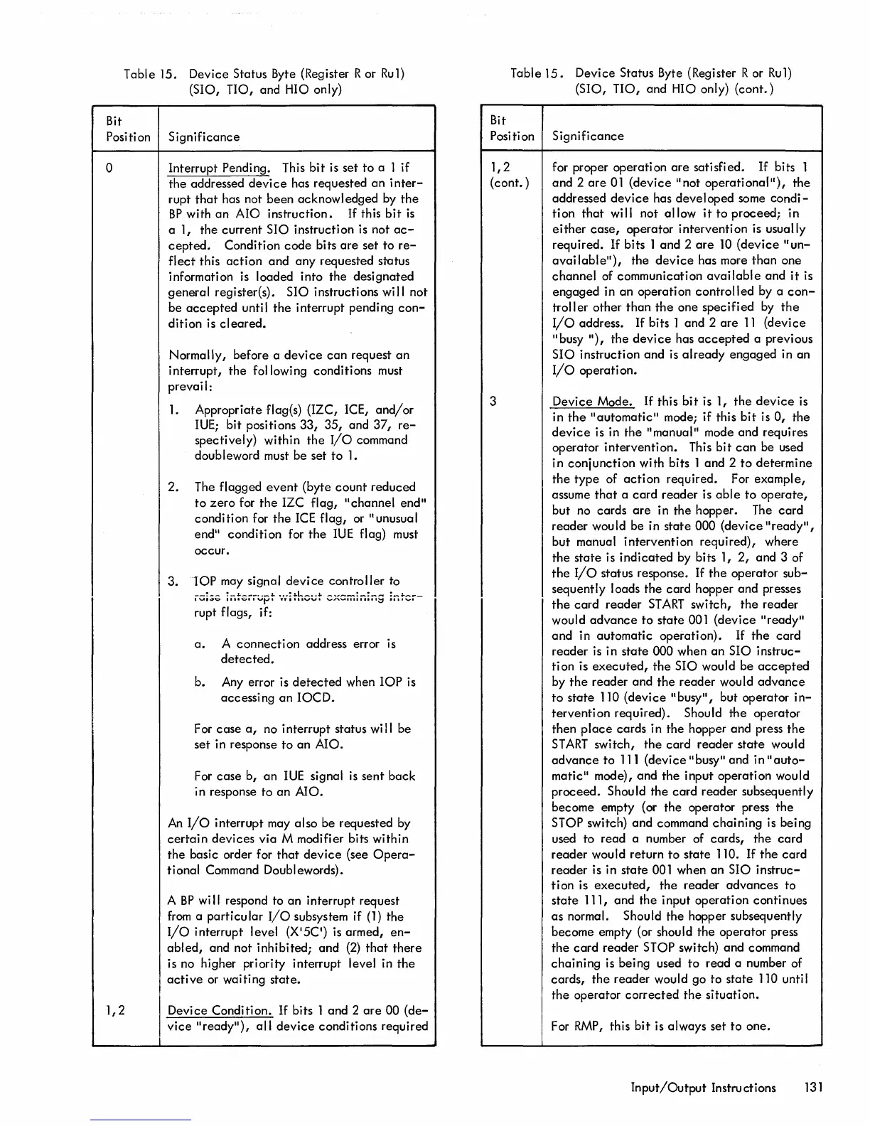
Table 15. Device Status Byte (Register R or Rul)
(510,
no,
and HIO only)
Position Significance
a Interrupt Pending. This
bit
is set
to
a 1 if
the
addressed
device
has requested
an
inter-
rupt
that
has not been acknowl edged by
the
BP
with
an
AIO instruction.
If
this
bit
is
1,2
a 1, the current 510 instruction is not
ac-
cepted.
Condition
code
bits
are
set to
re-
flect
this
action
and
any requested status
information
is
loaded into the designated
general register(s). 510 instructions
wi
II not
be
accepted
unti I
the
interrupt pendi
ng
con-
dition is
cleared.
Normally, before a
device
can
request
an
interrupt,
the
following conditions must
prevail:
1.
Appropriate flag(s) (IZC, ICE,
and/or
IUEi
bit positions
33,
35, and
37,
re-
spectively) within
the
I/o
command
doubleword must be set
to
1.
2. The flagged
event
(byte
count
reduced
to
zero
for
the
IZC flag, "channel end"
condition for
the
ICE
flag, or "unusual
end" condition for
the
IUE
flag) must
occur.
3.
lOP
may signal
device
controller to
__
~
__
!_""
___
..
_"
...
:""L_
..
.a.
_,,_
.......
:_:
__
:_""_
...
_
IUI~v
IIIICI'VtJl
YYIIIIVVI
"''''
......
III1II1.I~
1'11,,-,"1
rupt flags, if:
a.
A
connection
address error is
detected.
b.
Any
error is
detected
when
lOP
is
accessing
an
IOCD.
For
case
a,
no interrupt status
wi
II
be
set
in response to
an
AIO.
For
case
b,
an
IUE
signal
is
sent
back
in response to
an
AIO.
An
I/O
interrupt may also be requested
by
certain
devices
via M modifier bits within
the basic order for
that
device
(see
Opera-
tional Command Doublewords).
A
BP
wi
II
respond to an interrupt request
from
a
particular
I/O
subsystem if
(1)
the
I/O
interrupt level
(X
I
5C')
is
armed,
en-
abled,
and not inhibited; and
(2)
that
there
is no higher priority interrupt level in
the
active
or waiting
state.
Device Condition.
If
bits 1 and 2
are
00
(de-
vice
"
rea
d
y
"),
all
device
conditions required
Table
15.
Device Status Byte (Register R or
Ru1)
(510,
no,
and HIO only)
(cont.)
Bit
Position
1,2
(cont. )
3
Significance
for proper operation
are
satisfied.
If
bits 1
and 2
are
01
(device
"not
operational"),
the
addressed
device
has developed some
condi-
tion
that
wi
II
not allow
it
to proceed; in
either
case,
operator intervention is usually
required.
If
bits 1 and 2
are
10
(device
"un-
avai
lable"),
the
device
has more
than
one
channel of communication
available
and
it
is
engaged in an operation
controlled
by a
con-
troller
other
than
the
one
specified
by
the
I/O
address.
If
bits 1 and 2
are
11
(device
"busy
"),
the
device
has
accepted
a previous
510 instruction and is
already
engaged in an
I/O
operation.
Device Mode.
If
this
bit
is 1,
the
device
is
in
the
"automatic"
mode; if this
bit
is
a,
the
device
is in
the
"manual" mode and requires
operator intervention. This bit
can
be used
in
conjunction
with bits 1 and 2
to
determine
the
type
of
action
required. For example,
assume
that
a
card
reader
is
able
to
operate,
but no cards
are
in
the
hopper. The
card
reader
would be in
state
000
(device
"
rea
d
y
",
but manual intervention required), where
the
state
is
indicated
by bits 1,
2,
and 3 of
the
I/O
status response.
If
the
operator sub-
sequently loads
the
card
hopper and presses
the
card
reader
START
switch,
the
reader
would
advance
to
state
001 (device "
rea
d
y
"
and
in automatic operation).
If
the
card
reader
is in
state
000 when an 510 instruc-
tion is
executed,
the
510 would be
accepted
by
the
reader and
the
reader
would
advance
to
state
110 (device "busy", but operator
in-
tervention
required). Should
the
operator
then
place
cards in the hopper and press
the
START
switch,
the
card
reader
state
would
advance
to
111
(device
II
busy
II
and in "
au
to-
matic" mode), and
the
input operation would
proceed.
Should the
card
reader subsequently
become empty (or
the
operator press
the
STOP switch)
and
command
chaining
is being
used to read a number of cards,
the
card
reader would return
to
state
110.
If
the
card
reader
is in
state
001
when an 510 instruc-
tion is
executed,
the
reader
advances
to
state
111, and the input operation continues
as normal. Should
the
hopper subsequently
become empty (or should
the
operator press
the
card
reader STOP switch)
and
command
chaining
is being used
to
read a number of
cards,
the
reader would go to
state
110 unti I
the
operator
corrected
the
situation.
For
RMP,
this
bit
is always set to one.
Input/Output
Instructions
131

 Loading...


