42 www.xilinx.com ChipScope Pro Software and Cores User Guide
UG029 (v14.3) October 16, 2012
Chapter 3: Using the ChipScope Pro Core Inserter
Use the TRIGn Match Type pull-down list to select the type of match unit that will apply to
all match units connected to the trigger port. However, as the functionality of the match
unit increases, so does the amount of resources necessary to implement that functionality.
This flexibility allows you to customize the functionality of the trigger module while
keeping resource usage in check.
Selecting Match Unit Counter Width
The match unit counter is a configurable counter on the output of the each match unit in a
trigger port. This counter can be configured at runtime to count a specific number of match
unit events. To include a match counter on each match unit in the trigger port, select a
counter width from 1 to 32. The match counter is not included on each match unit if the
Counter Width combo box is set to Disabled. The default Counter Width setting is
Disabled.
Enabling the Trigger Condition Sequencer
The trigger condition sequencer is a standard Boolean equation trigger condition that can be
augmented with an optional trigger sequencer by checking the Enable Trigger Sequencer
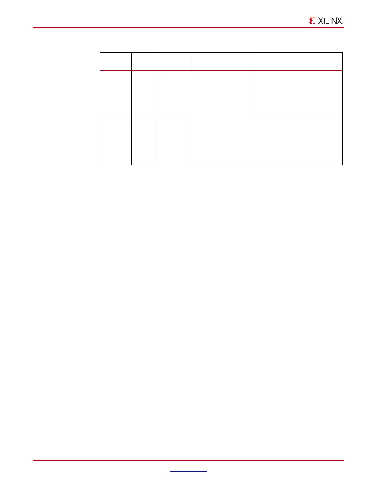
Range 0, 1, X
‘=’, ‘<>’,
‘>’, ‘>=’,
‘<‘, ‘<=’,
‘in range’,
‘not in
range’
LUT4-based: 1
LUT6-based: 8
Can be used for comparing
address or data signals where a
range of values is important.
Range
w/edges
0, 1, X,
R, F, B,
N
‘=’, ‘<>’,
‘>’, ‘>=’,
‘<‘, ‘<=’,
‘in range’,
‘not in
range’
LUT4-based: 1
LUT6-based: 4
Can be used for comparing
address or data signals where a
range of values and transition
detection are important.
Notes:
1. Bit values: ’0’ = “logical 0”; ‘1’ =“logical 1”; ‘X’ =“don’t care”; ‘R’= “0-to-1 transition”; ‘F’= “1-to-0
transition”; ‘B’= “any transition”; ‘N’ = “no transition”.
2. The Bits Per Slice value is only an approximation that is used to illustrate the relative resource
utilization of the different match unit types. It should not be used as a hard estimate of resource
utilization. LUT4-based device families are Spartan-3, Spartan-3E, Spartan-3A, Spartan-3A DSP, and
Virtex-4 FPGAs (and the variants of these families). LUT6-based device families are Zynq™- 7000 AP
SoCs. and Virtex-5, Virtex-6, Spartan-6, Artix™-7, Kintex™-7, and Virtex-7
FPGAs.
Table 3-1: ILA Trigger Match Unit Types (Cont’d)
Type
Bit
Values
1
Match
Function
Bits Per Slice
2
Description