Zynq-7000 PCB Design Guide www.xilinx.com 43
UG933 (v1.8) November 7, 2014
Chapter 4: SelectIO Signaling
In general, parallel resistive termination (R
P
) has a value equal to the characteristic
impedance (Z
0
) of the transmission line it is terminating. Series resistive terminations (R
S
)
have a value equal to the characteristic impedance of the transmission line (Z
0
) minus the
output impedance of the driver (R
O
) to which they are connected. Controlled-impedance
drivers are tuned such that the driver output impedance (R
O
) is equal to the characteristic
impedance (Z
0
) of the transmission line it is terminating.
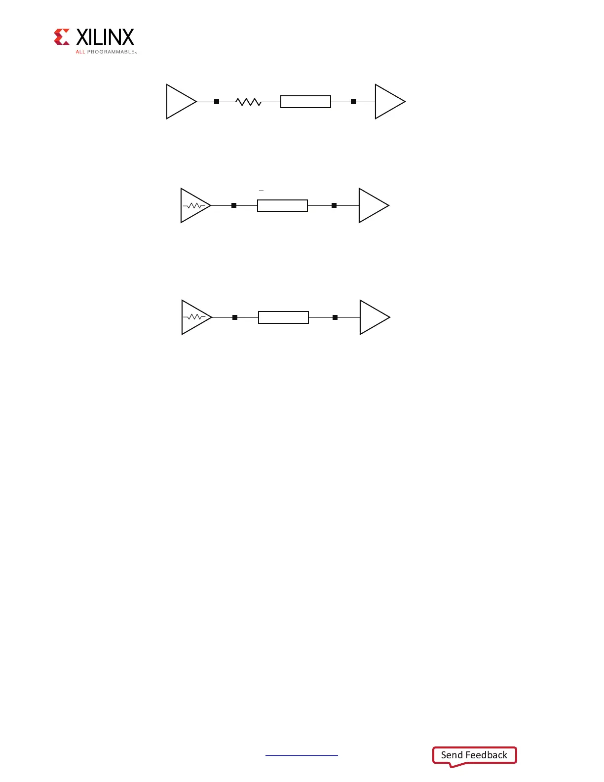
Assuming transmission lines with 50Ω characteristic impedance and a driver output
impedance (R
O
) of 25Ω , a 25Ω series termination (Figure 4-2) or a 50Ω parallel termination
(Figure 4-1) is appropriate. Controlled-impedance drivers, whether implemented with DCI
or with weak LVCMOS drivers, should be sized to have an output impedance (R
O
) of 50Ω .
This corresponds to VRN and VRP resistors equal to 50Ω for DCI. Weak LVCMOS drivers of
6 mA to 8 mA drive strength have an output impedance approximately equal to
50Ω (Figure 4-3).
Typically, parallel terminations have best performance when V
TT
(the voltage source
connected to the parallel termination resistor) is equal to half of the signaling voltage. For
2.5V signals (V
CCO
= 2.5V), V
TT
is ideally 1.25V. In cases where this voltage is not available,
it is possible to use a Thevenin parallel termination. Thevenin parallel termination consists
of a voltage divider with a parallel equivalent resistance (R
PEQ
) equal to the characteristic
impedance of the transmission line (50Ω in most cases). The divided voltage point is
designed to be at V
TT
. Figure 4-5 illustrates a Thevenin parallel termination powered from
2.5V V
CCO
, made up of two 100Ω resistors, resulting in a V
TT
of 1.25V and a parallel
equivalent resistance (R
PEQ
) of 50Ω .
X-Ref Target - Figure 4-2
Figure 4-2: Series-Terminated Unidirectional, Point-to-Point Topography
X-Ref Target - Figure 4-3
Figure 4-3: DCI-Controlled Impedance Driver Unidirectional, Point-to-Point
Topography
X-Ref Target - Figure 4-4
Figure 4-4: “Weak Driver” Unidirectional, Point-to-Point Topography
UG933_c4_02_031711
R
S
= Z
0
– R
0
= 25Ω
Z
0
= 50Ω
R
O
= 25Ω
UG933_c4_03_031711
LVDCI
Z
0
= 50Ω
R
O
= R
VRN
= R
VRP
> Z
0
=
50Ω
UG933_c4_04_031711
LVCMOS (DRIVE = 6, SLEW = FAST)
Z
0
= 50Ω
R
O
≈ Z
0
~ 50Ω
 Loading...


