Zynq-7000 PCB Design Guide www.xilinx.com 2
UG933 (v1.8) November 7, 2014
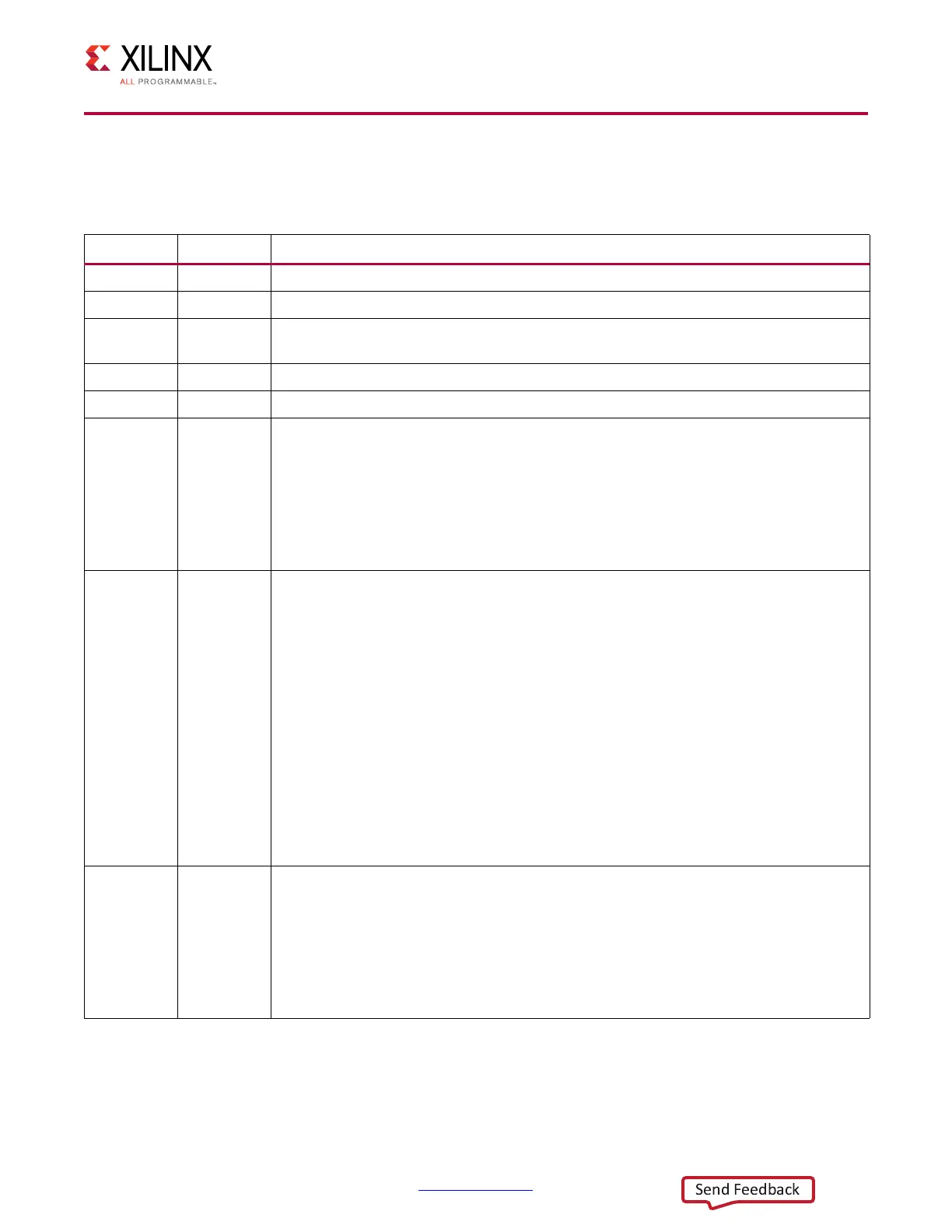
Revision History
The following table shows the revision history for this document.
Date Version Revision
06/04/2012 1.0
Initial Xilinx release.
06/06/2012 1.1
Corrected format issue.
08/29/2012 1.2
Updated Table 3-1 and Table 3-2 for additional devices/packages. Added 680 µF
capacitor specification to Table 3-3.
10/11/2012 1.2.1
Corrected document number (changed UG993 to UG933).
11/05/2012 1.2.2
Corrected sizing problem in PDF (no content change).
02/12/2013 1.3
Added Note
(2)
to Tab le 3-2. Added suggested part numbers to Table 3-3. Modified
paragraph under V
CCPAUX
– PS Auxiliary Logic Supply. Modified paragraph under
V
CCPLL
– PS PLL Supply. Added Figure 5-3. Modified second to last sentence and
added last sentence under PS_DDR_VREF0, PS_DDR_VREF1 – PS DDR Reference
Voltage. Modified CAUTION! under Configuring the V
CCO_MIO0
, V
CCO_MIO1
Voltage
Mode and Note under DDR Supply Voltages. Changed Cke connection from a
pull-down resistor to a pull-up resistor in Figure 5-5 through Figure 5-7. Updated
entire MIO/EMIO IP Layout Guidelines section.
04/01/2013 1.4
Added XC7Z100 devices to Table 3-1 and Tab le 3-2. Updated ESR range values in
Tabl e 3-3. Changed “0805 Ceramic Capacitor” section heading to Mid and High
Frequency Capacitors and modified first paragraph. Removed dimensions, changed
“0805” to “0402” in Figure 3-1 and deleted “0402 Ceramic Capacitor” subsection.
Deleted last sentence under , Modes and Attributes. Changed “minimum” to
“maximum” in third sentence of second paragraph under V
CCPLL
– PS PLL Supply.
Added second to last sentence under PS_DDR_VREF0, PS_DDR_VREF1 – PS DDR
Reference Voltage. Changed “Rup” to “Rterm” in Figure 5-5 and Figure 5-6. Deleted
Drst_b from Figure 5-6 and Figure 5-7. Changed Rup pull-up resistor to Rdown
pull-down resistor in Figure 5-7. Changed LPDDR2 setting in last row of Tabl e 5- 6 to
N/A. Updated values in first row of Tabl e 5-9. Changed “Three” different topologies
to “two” under DDR Routing Topology. Removed Fly-by topology from Figure 5-8 and
Tabl e 5-12. Deleted “NAND (ONFI),” “NOR/Flash/SRAM,” “SPI Master,” “SWDT (System
Watch Dog Timer),” and “TTC (Triple Time Counter” subsections from MIO/EMIO IP
Layout Guidelines and modified remaining subsections. Changed “EN208” to “EN247”
and “DS821” to “PG054” under Additional Resources and Legal Notices in Appendix A.
09/26/2013 1.5
Added XC7Z010, XC7Z015, and XC7Z030 packages/devices to Table 3-1 and Tabl e 3-2.
Changed suggested part number for the 4.7 µF capacitor in Tab le 3-3. Added DDR ECC
unused pins to Tab le 5-5. Modified Figure 5-6 (Cke pins are now applied to GND via
resistor Rdown instead of VTT via Rterm). Expanded first paragraph under DDR
Termination. Clarified DDR Termination paragraph. Added fly-by routing to DDR
Routing Topology section. Deleted SD/SDIO Peripheral Controller section. Added last
sentence under sections IIC and SDIO and second sentence under QSPI. Added
Chapter 6, Migration from XC7Z030-SBG485 to XC7Z015-CLG485 Devices.
 Loading...


