Zynq-7000 PCB Design Guide www.xilinx.com 58
UG933 (v1.8) November 7, 2014
Chapter 5: Processing System (PS) Power and Signaling
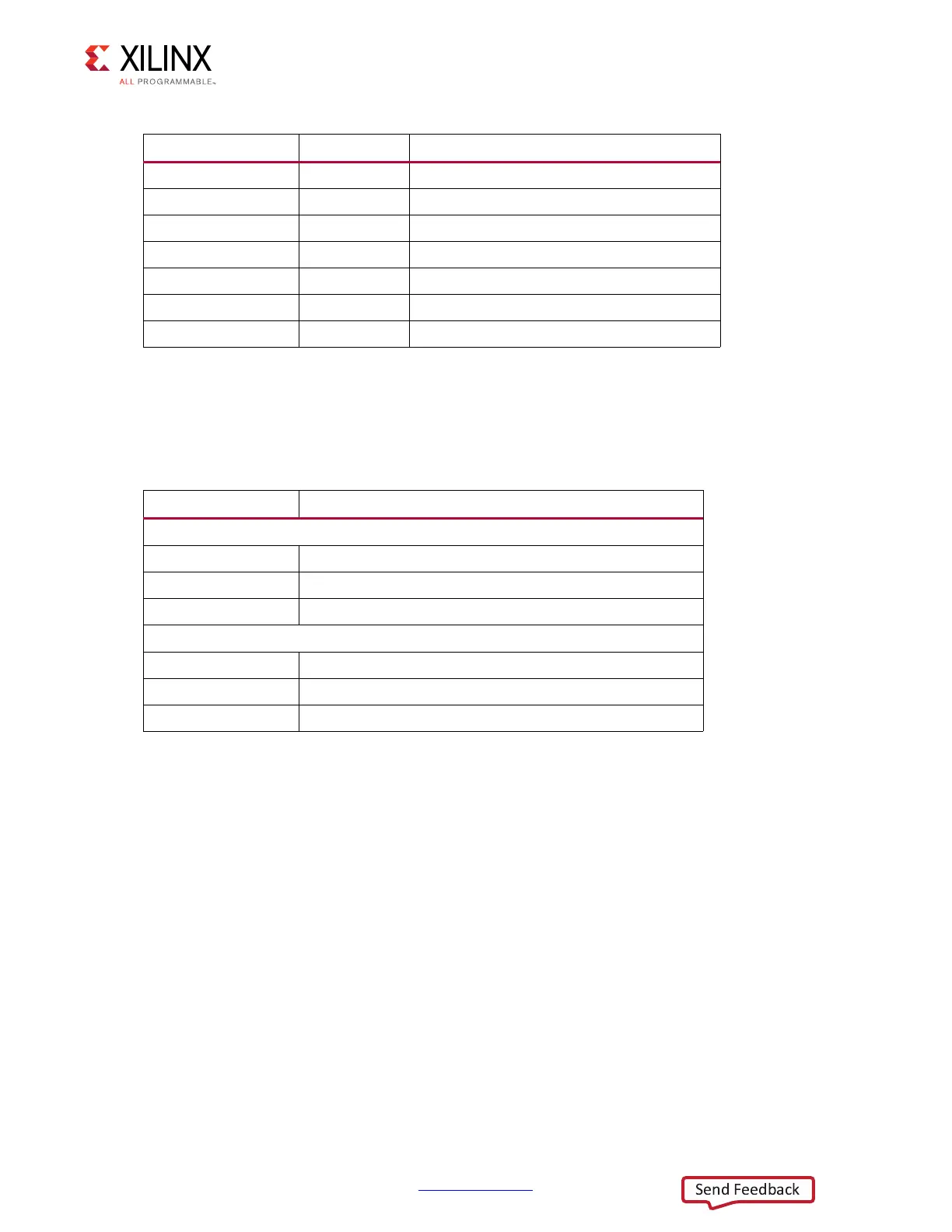
Unused DDR pins should be connected as shown in Table 5- 5 .
For designs utilizing single-ended DQS, connect the DQS signal to DQS_P. DQS_N can either
be connected to the DQS_B I/O of the SDRAM, or via resistor divider to VCCO/2.
Dynamic Memory Implementation
Figure 5-5, Figure 5-6 and Figure 5-7 show examples of implementing DDR memory on
typical boards.
DDR_DQ[31:0] I/O Data
DDR_DM[3:0] O Data mask
DDR_DQS_P[3:0] I/O Differential data strobe positive
DDR_DQS_N[3:0] I/O Differential data strobe negative
DDR_VRP I/O Used to calibrate input termination
DDR_VRN I/O Used to calibrate input termination
DDR_VREF[1:0] I/O Reference voltage
Table 5-5: DDR Unused Pins
Unconnected Pins Comments
DDR Unused Pins, x16 non-ECC
O Unconnected
DQ/DQS IO Unconnected, internal pull-up by software
IO Unconnected, internal pull-up by software
DDR Unused Pins, x16 ECC
O Unconnected
DQ/DQS IO Connect to SDRAM
Other IO Unconnected, internal pull-up by software
Table 5-4: DDR Interface Signal Pins (Cont’d)
Pin Name Direction Description
 Loading...


