Zynq-7000 PCB Design Guide www.xilinx.com 48
UG933 (v1.8) November 7, 2014
Chapter 4: SelectIO Signaling
In general, parallel resistive termination (R
P
) has a value equal to the characteristic
impedance Z
0
of the transmission line it is terminating. Some interfaces, such as DDR2
memory interfaces, use 75Ω termination resistors instead of 50Ω in an effort to open the
data eye. In this case, the trade-off is eye height against a small amount of signal reflection
from the impedance discontinuity. Controlled-impedance drivers are typically tuned such
that the driver output impedance (R
O
) is equal to the characteristic impedance (Z
0
) of the
transmission line it is terminating.
Assuming transmission lines with 50Ω characteristic impedance and a driver output
impedance of 25Ω , 50Ω parallel terminations are appropriate (Figure 4-7).
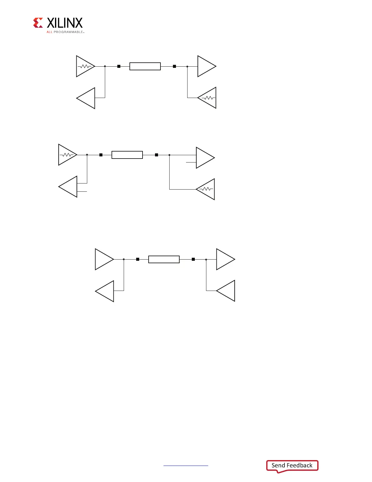
Controlled-impedance drivers, whether implemented with DCI or with weak LVCMOS
drivers, should be sized to have an output impedance (R
O
) of 50Ω . An example of the use
of a controlled-impedance driver would be the LVDCI_15 I/O standard. By using 50Ω
X-Ref Target - Figure 4-9
Figure 4-9: DCI Controlled Impedance Bidirectional Point-to-Point Topography
X-Ref Target - Figure 4-10
Figure 4-10: HSLVDCI Controlled Impedance Driver Bidirectional Point-to-Point
Topography
X-Ref Target - Figure 4-11
Figure 4-11: “Weak Driver” Bidirectional Point-to-Point Topography
UG933_c4_09_032411
LVDCI_15
LVDCI_15
Z
0
= 50Ω
R
O
= R
VRN
= R
VRP
≈ Z
0
= 50Ω
R
O
= R
VRN
= R
VRP
≈ Z
0
= 50Ω
UG933_c4_10_032411
LVDCI_DIV2_15
LVDCI_DIV2_15
V
REF
V
REF
Z
0
= 50Ω
R
O
= 0.5 x R
VRN
= 0.5 x R
VRP
≈ Z
0
= 50Ω
R
O
= 0.5 x R
VRN
= 0.5 x R
VRP
≈ Z
0
= 50Ω
UG933_c4_11_031711
LVCMOS (DRIVE = 6, SLEW = FAST)
Z
0
= 50Ω
R
O
≈ Z
0
= 50Ω
LVCMOS_6F
R
O
≈ Z
0
= 50Ω
 Loading...


