Zynq-7000 PCB Design Guide www.xilinx.com 44
UG933 (v1.8) November 7, 2014
Chapter 4: SelectIO Signaling
Parallel termination can be less desirable than series termination or controlled-impedance
drivers because it dissipates more power. This trade-off must be weighed against other
trade-offs to determine the optimum termination topography for an interface.
Table 4-1 lists example I/O interface types that can be used with the unidirectional
point-to-point topography.
LVTTL and LVCMOS do not specify any canonical termination method. Series termination at
the driver or parallel termination at the receiver are both appropriate considerations.
LVDCI implicitly uses controlled-impedance driver termination. No form of termination is
needed at the receiver.
Every I/O standard can have different requirements for termination techniques. In some
cases the specification for the I/O standard can rigidly define the termination topology.
Other standards might not have any hard requirements, but rather might simply provide
examples of termination topologies. An example of a standard with specific termination
requirements is HSTL. HSTL Class I is a unidirectional I/O standard that recommends a
parallel termination at the receiver. In the case of HSTL Class I, the termination voltage V
TT
is defined as half of the supply voltage V
CC
. The designer can ultimately elect either not to
use termination at all or to use a different termination, such as series termination at the
driver. There are a number of reasons why this selection might be advantageous in a given
system. It is up to the designer to verify through simulation and measurement that the
signal integrity at the receiver is adequate.
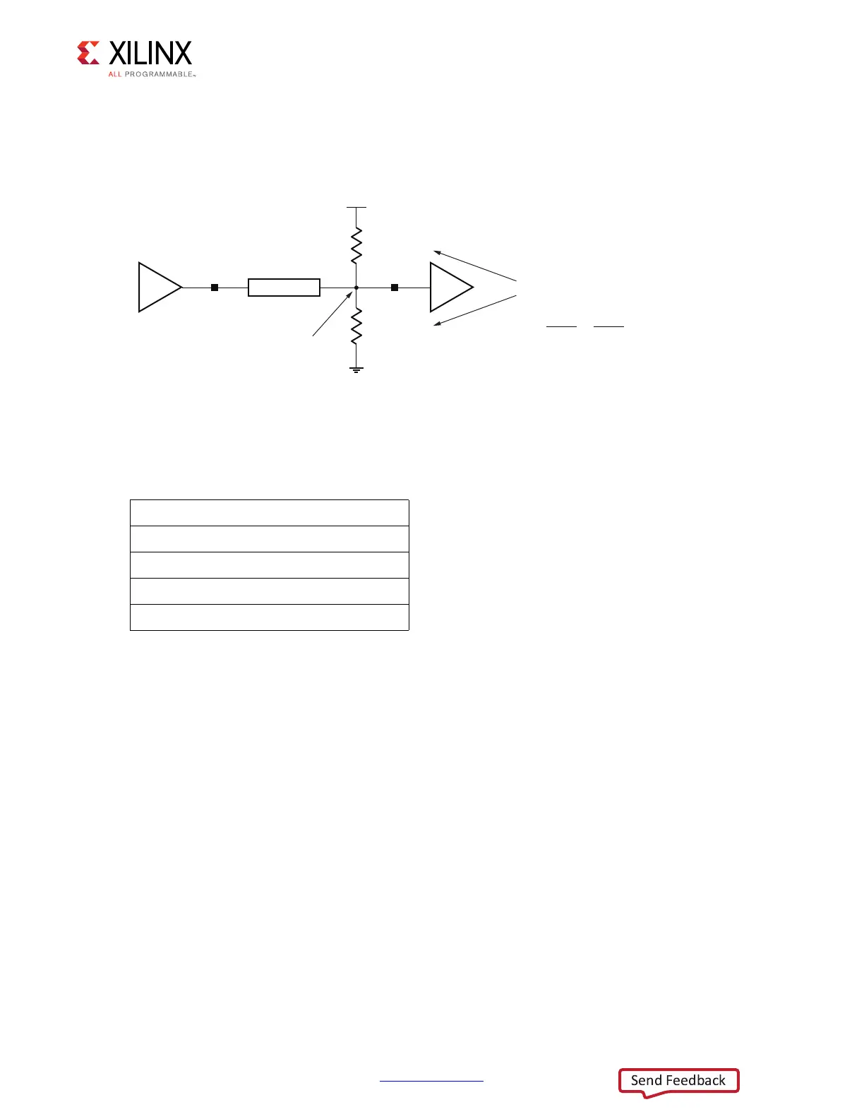
X-Ref Target - Figure 4-5
Figure 4-5: Thevenin Parallel Termination
Table 4-1: Example I/O Interface Type for Unidirectional Point-to-Point Topographies
LVTTL
LVC MOS
LVDCI
SSTL Class I
HSTL Class I
UG933_c4_05_031711
R
PT
= 2 x Z
0
= 100Ω
R
PT
= 2 x Z
0
= 100Ω
V
CCO
= 2.5V
Parallel Equivalent Resistance
V
TTEQ
= 1.25V
R
PEQ
=
(
1
100Ω
1
100Ω
+
)
–1
= 50Ω
Z
0
= 50Ω
R
O
= 25Ω
 Loading...


