Zynq-7000 PCB Design Guide www.xilinx.com 15
UG933 (v1.8) November 7, 2014
Chapter 3: Power Distribution System
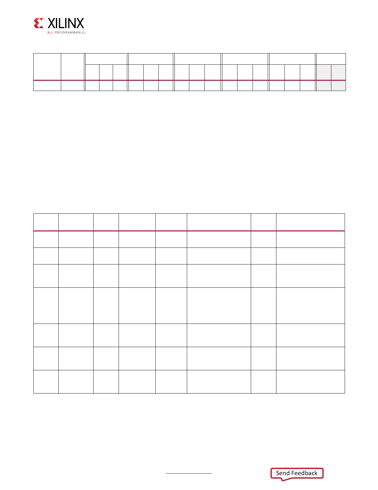
Capacitor Specifications
The electrical characteristics of the capacitors in Table 3-1 and Table 3-2 are specified in
Table 3-3, and are followed by guidelines on acceptable substitutions. The equivalent series
resistance (ESR) ranges specified for these capacitors can be over-ridden. However, this
requires analysis of the resulting power distribution system impedance to ensure that no
resonant impedance spikes result.
FFG1156 Z-7100 1 0 0 1 1 1 1 0 0 1 1 1 1 1 1
Notes:
1. See V
CCPAUX
– PS Auxiliary Logic Supply, page 51 for layout guidelines.
2. V
CCPLL
can be derived from V
CCPAUX
using a ferrite bead filter (see Figure 5-2, page 52).
3. See V
CCPLL
– PS PLL Supply, page 52 for layout guidelines.
Table 3-2: Required PCB Capacitor Quantities per Device (PS) (Cont’d)
Package Device
V
CCPINT
V
CCPAUX
(1)
V
CCO_DDR
V
CCO_MIO0
V
CCO_MIO1
V
CCPLL
(2)(3)
100
µF
4.7
µF
0.47
µF
100
µF
4.7
µF
0.47
µF
100
µF
4.7
µF
0.47
µF
100
µF
4.7
µF
0.47
µF
100
µF
4.7
µF
0.47
µF
Table 3-3: PCB Capacitor Specifications
Ideal
Value
Value
Range
(1)
Body
Size
(2)
Type
ESL
Maximum
ESR Range
(3)
Voltage
Rating
(4)
Suggested
Part Number
680 µF C > 680 µF 2917/D
/7343
2-Terminal
Tantalum
2.1 nH 5 mΩ < ESR < 40 mΩ 2.5V T530X687M006ATE018
330 µF C > 330 µF 2917/D
/7343
2-Terminal
Tantalum
2.0 nH 5 mΩ < ESR < 40 mΩ 2.5V T525D337M006ATE025
330 µF C > 330 µF 2917/D
/7343
2-Terminal
Niobium
Oxide
2.0 nH 5 mΩ < ESR < 40 mΩ 2.5V NOSD337M002#0035
100µF C > 100µF 1210 2-Terminal
Tantalum,
Ceramic
X7R, X7U, or
X5R
1nH 1mΩ < ESR < 40 mΩ 2.5V GRM32EE70G107ME19
47 µF C > 47 µF 1210 2-Terminal
Ceramic X7R
or X5R
1nH 1mΩ < ESR < 40 mΩ 6.3V GRM32ER70J476ME20L
10 µF C = 10 µF 0603 2-Terminal
Ceramic X7R
or X5R
0.25 nH 5 mΩ 4.0V GRM188R60G106ME47
4.7 µF C > 4.7 µF 0805 2-Terminal
Ceramic X7R
or X5R
0.5 nH 1 mΩ < ESR < 20 mΩ 6.3V GRM21BR71A475KA73
 Loading...


