Zynq-7000 PCB Design Guide www.xilinx.com 52
UG933 (v1.8) November 7, 2014
Chapter 5: Processing System (PS) Power and Signaling
capacitor to the adjacent V
CCPAUX
and GND BGA vias. This supply can be combined with
V
CCAUX
if the system does not require the PL supply to be powered down independent of
the PS.
V
CCPLL
– PS PLL Supply
V
CCPLL
is a 1.8V nominal supply that provides power to the three PS PLLs and additional
analog circuits. It can be powered separately or derived from the V
CCPAUX
supply. If powered
by V
CCPAUX
, V
CCPLL
must be filtered through a 120Ω @ 100 MHz, size 0603 ferrite bead and
a 10 µF or larger, size 0603 decoupling capacitor. In both cases a 0.47 µF to 4.7 µF 0402
capacitor must be placed near the V
CCPLL
BGA via.
The PCB construction of the V
CCPLL
power supply must be carefully managed. The
recommended connection between the 10 µF 0603 capacitor and the V
CCPLL
BGA ball is a
planelet with a minimum width of 80 mil (2 mm) and a length of less than 3,000 mil
(76 mm). If a planelet cannot be used then a trace with a maximum impedance of 40Ω and
a length of less than 2,000 mil (50.8mm) must be used. The 0.47 µF to 4.7 µF 0402 or 0201
capacitor must have a less than a 200 mil (5.1 mm) total PCB trace length from the capacitor
to the adjacent V
CCPLL
and GND BGA vias.
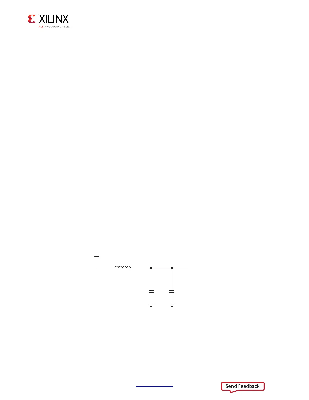
Figure 5-2 shows an example of the filtering and local capacitor circuit used when V
CCPLL
is
derived from V
CCPAUX
. Figure 5-3 shows an example of the layout of the same filtering
circuit for the CLG484 package.
The recommended components are:
• Ferrite bead – Murata BLM18SG121TN1
• 10 µF capacitor – Murata GRM188R60G106ME47
• 0.47µF-4.7µF capacitor – Murata GRM155R60J474KE19
X-Ref Target - Figure 5-2
Figure 5-2: Connecting V
CCPLL
FERRITE-120
V
CCPLL
10 µF
UG933_c5_02_020813
GND
V
CCPAUX
0.47-4.7 µF
GND
 Loading...


