Zynq-7000 PCB Design Guide www.xilinx.com 36
UG933 (v1.8) November 7, 2014
Chapter 3: Power Distribution System
Optimum Decoupling Network Design
If a highly optimized PDS is needed, measurements and simulations of a prototype system
can inform the PDS design. Using knowledge of the noise spectrum generated by the
prototype system along with knowledge of the system’s power system impedance, the
unique transient current of the design can be determined and accommodated.
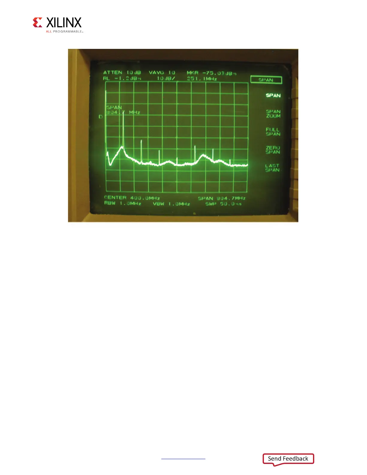
To measure the noise spectrum of the design under operating conditions, use either a
spectrum analyzer or an oscilloscope with FFT. The power system impedance can be
determined either through direct measurement or simulation, or a combination of these
two as there are often many variables and unknowns.
Both the noise spectrum and the impedance are functions of frequency. By examining the
quotient of these per frequency point, transient current as a function of frequency is
computed (Equation 3-7):
Equation 3-7
Using the data sheet’s maximum voltage ripple value, the impedance value needed at all
frequencies can be determined. This yields a target impedance as a function of frequency. A
X-Ref Target - Figure 3-10
Figure 3-10: Screenshot of Spectrum Analyzer Measurement of V
CCO
If()
Vf()From Spectrum Analyzer
Zf()From Network Ana lyzer
-------------------------------------------------------------------------------------=
 Loading...


