BRKT
7-33
6885J11
Bracket unit
5. Tighten the self-locking nut 8 to the
specified torque.
6. Install the ground lead 9, anode 0 and
tilt pin q.
7. Pass the PTT motor lead w through the
hole of the port clamp bracket.
8. Fasten the PTT motor lead and trim sen-
sor lead with the lock ties e.
9. Inject grease into all grease nipples until
grease comes out from the bushings a.
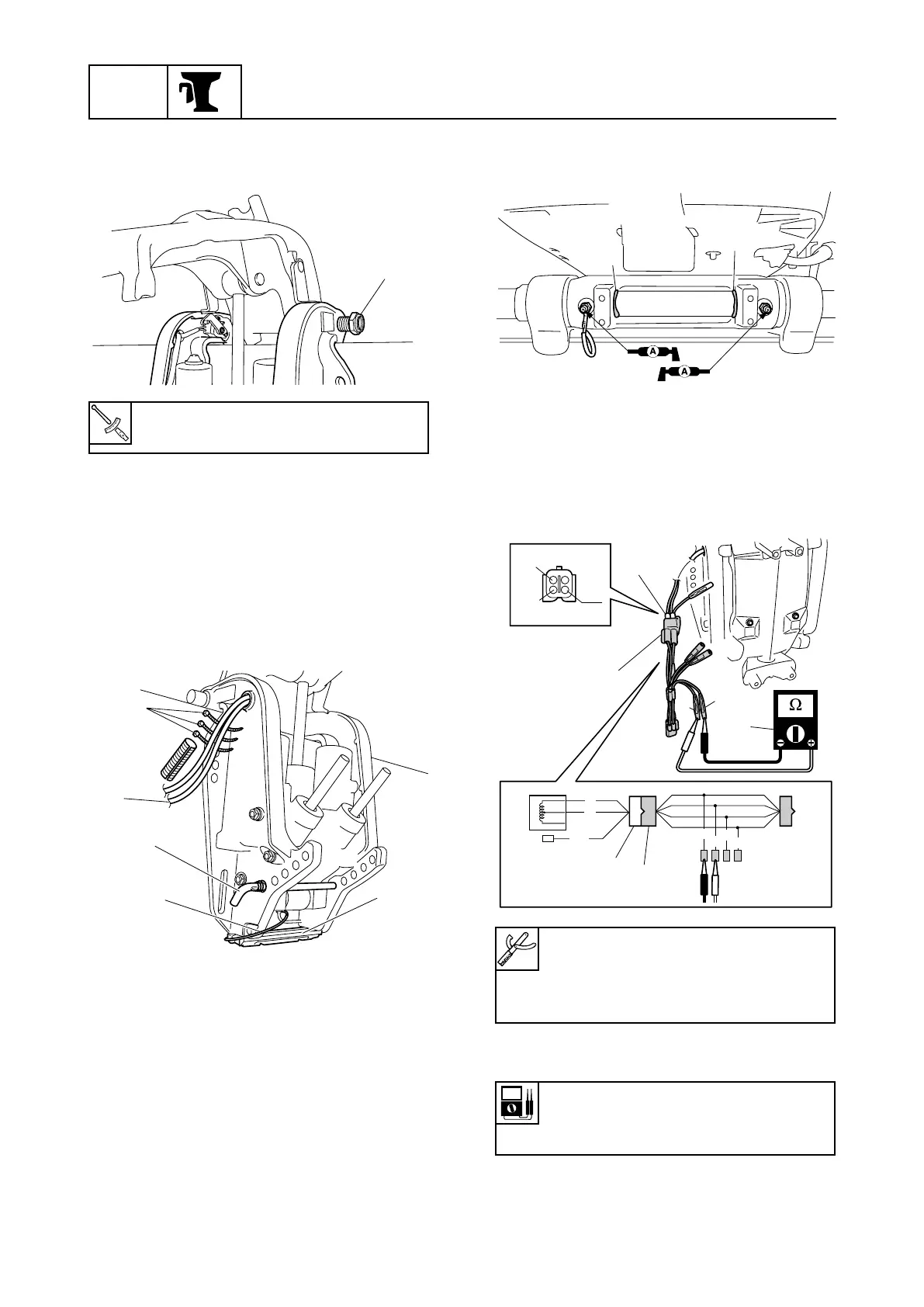
Adjusting the trim sensor cam (ET)
1. Fully tilt the outboard motor down.
2. Connect the test harness 1 to the trim
sensor coupler 2.
3. Measure the trim sensor resistance.
4. If the trim sensor resistance is out of
specification, adjust the trim sensor.
Self-locking nut 8:
15 N·m (1.5 kgf·m, 11.1 ft·lb)
68870500
9
q
w
e
0
B
P
Gy
G
R
Br
B
68870520
Gy
P
B
2
1
G
R
2
1
3
Test harness 1:
90890-06878
Digital circuit tester 3:
90890-03174
Trim sensor setting resistance:
Pink (P)–Black (B)
9–11 Ω
6885J11_07a 07.10.12 15:16 Page 36