Checking the thermoswitch
1. Remove the thermoswitch from cylinder
head.
NOTE:
To remove the thermoswitch, refer to page 5-
18.
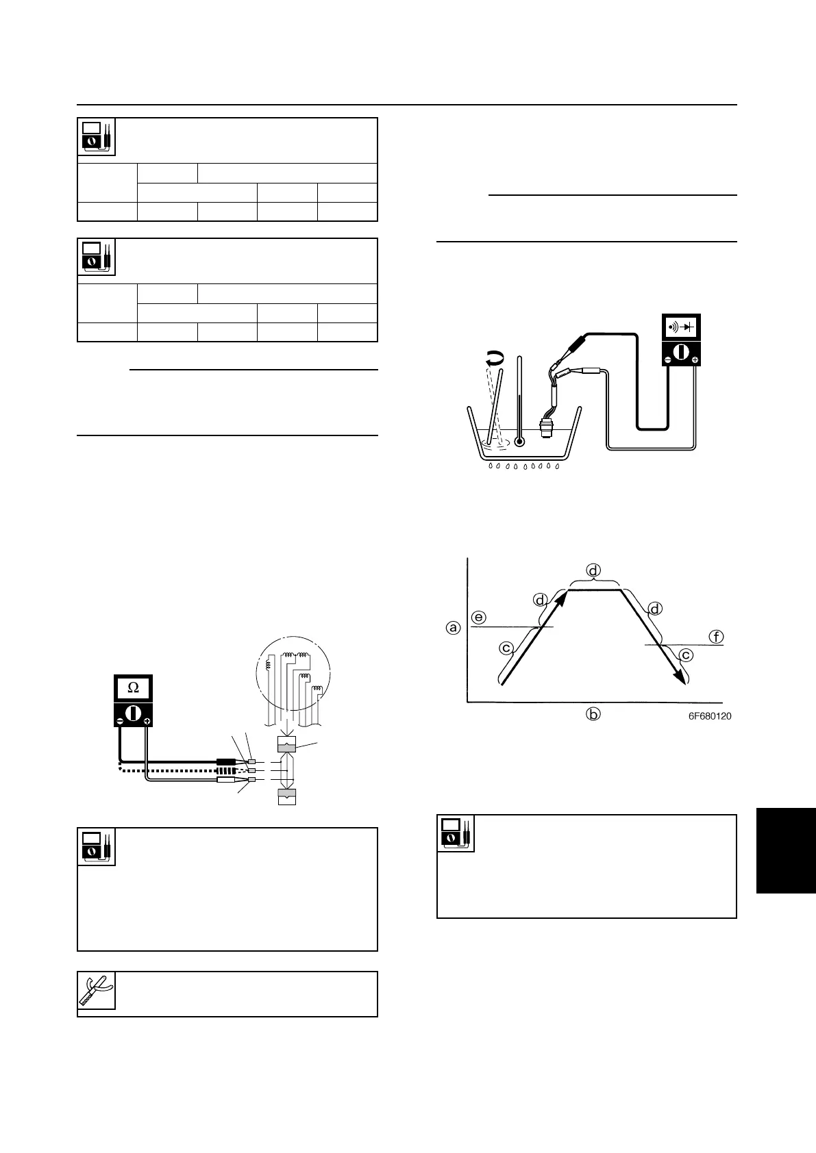
2. Place the thermoswitch in a container of
water and slowly heat the water.
3. Check the switch for continuity at the
specified temperatures. Replace the ther-
moswitche if out of specification.
a Temperature
b Time
c No continuity
d Continuity
6885J11
8-8
9
8
7
6
5
4
3
2
1
Ignition and ignition control system
NOTE:
Remove the all spark plug caps, when mea-
suring the charge coil peak voltage at loaded
engine cranking.
4. Disconnect the charge coil coupler.
5. Connect the special service tool 1 and
digital circuit tester to the charge coil cou-
pler.
6. Measure the charge coil resistance.
Replace the stator assembly if out of
specification.
Charge coil resistance
(reference data):
Red (R)–Brown (Br)
48–72 Ω at 20°C (68°F)
Red (R)–Blue (L)
428–642 Ω at 20°C (68°F)
Thermoswitch continuity
temperature (reference data):
Pink (P)–Black (B)
e:84–90 °C (183–194°F)
f:60–74 °C (140–165°F)
Charge coil output peak voltage:
Red (R)–Blue (L)
r/min
Unloaded
Loaded
Cranking 1,500 3,500
DC V 150 110 150 160
Charge coil output peak voltage:
Red (R)–Brown (Br)
r/min
Unloaded
Loaded
Cranking 1,500 3,500
DC V 50 60 150 160
Throttle sensor adjusting lead 1:
90890-06857
6885J11_08 07.10.1 9:02 Page 9