6885J11
7-58
9
8
7
6
5
4
3
2
1
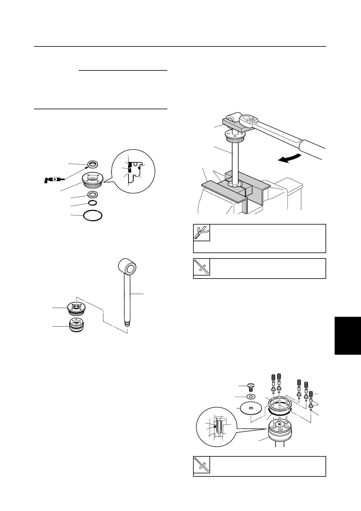
Tilt cylinder and trim cylinder
3. Hold the tilt piston in a vice using the alu-
minum plates a and special service tool
8 on both sides.
4. Tighten the tilt ram 7 to the specified
torque.
5. Install the new O-ring 0 and backup ring
q onto the tilt piston 6.
6. Install the balls w, absorber valve pins
e, and springs r as shown.
7. Install the washer t, plate y, and bolt u
to the tilt piston 6, and then tighten the
bolt to the specified torque.
PTT piston vice attachment 8:
90890-06572
Tilt rod wrench 9: 90890-06569
Tilt ram 7:
65 N·m (6.5 kgf·m, 47.9 ft·lb)
Tilt piston bolt u:
13 N·m (1.3 kgf·m, 9.6 ft·lb)
8
7
9
a
68871140
6
q
t
r
u
y
e
q
6
0
r
e
w
0
w
68871150
Assembling the tilt ram
cC
Do not use a rag when assembling the
PTT unit as dust and particles on the PTT
unit components can lead to poor perfor-
mance.
1. Install the new dust seal 1, new O-rings
2, 3, and backup ring 4 into the tilt
cylinder end screw 5.
2. Install the tilt cylinder end screw 5, and
tilt piston 6 to the tilt ram 7.
6885J11_07b_1 07.10.1 9:04 Page 25
 Loading...