BRKT
7-65
6885J11
Bracket unit
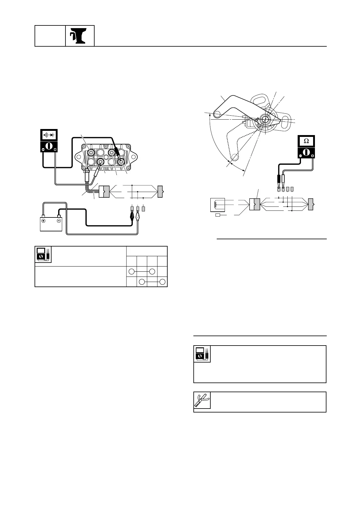
6. Connect the sky blue (Sb) lead to the
positive battery terminal and the black (B)
lead to the negative battery terminal as
shown.
7. Check for continuity between terminals.
Replace the PTT relay if not shown in the
chart below.
Tester probe
Terminal
3456
Terminal–Terminal
R
O
P
R
P
O
3
5
6
4
B
Lg
Sb
68871340
Checking the trim sensor
1. Measure the trim sensor resistance.
Replace if out of specification.
NOTE:
9 Turn the trim sensor lever 1 from a to c
and measure the resistance as it gradually
changes.
9 The position b is the trim sensor lever posi-
tion when the outboard motor is tilted down.
To adjust the trim sensor, refer to page
7-33.
9 The trim sensor resistance will be lower at
the position c than at the position b.
9 The range d is the trim and tilt operation
range.
B
P
Gy
G
R
Br
B
G R Br B
a
c
b
d
1
2
68871350
Trim sensor resistance:
Pink (P)–Black (B)
168.3–288.3 Ω at a
9–11 Ω at b
Test harness 2:
90890-06878
6885J11_07b_1 07.10.1 9:04 Page 32