6885J11
5-10
9
8
7
6
5
4
3
2
1
Power unit
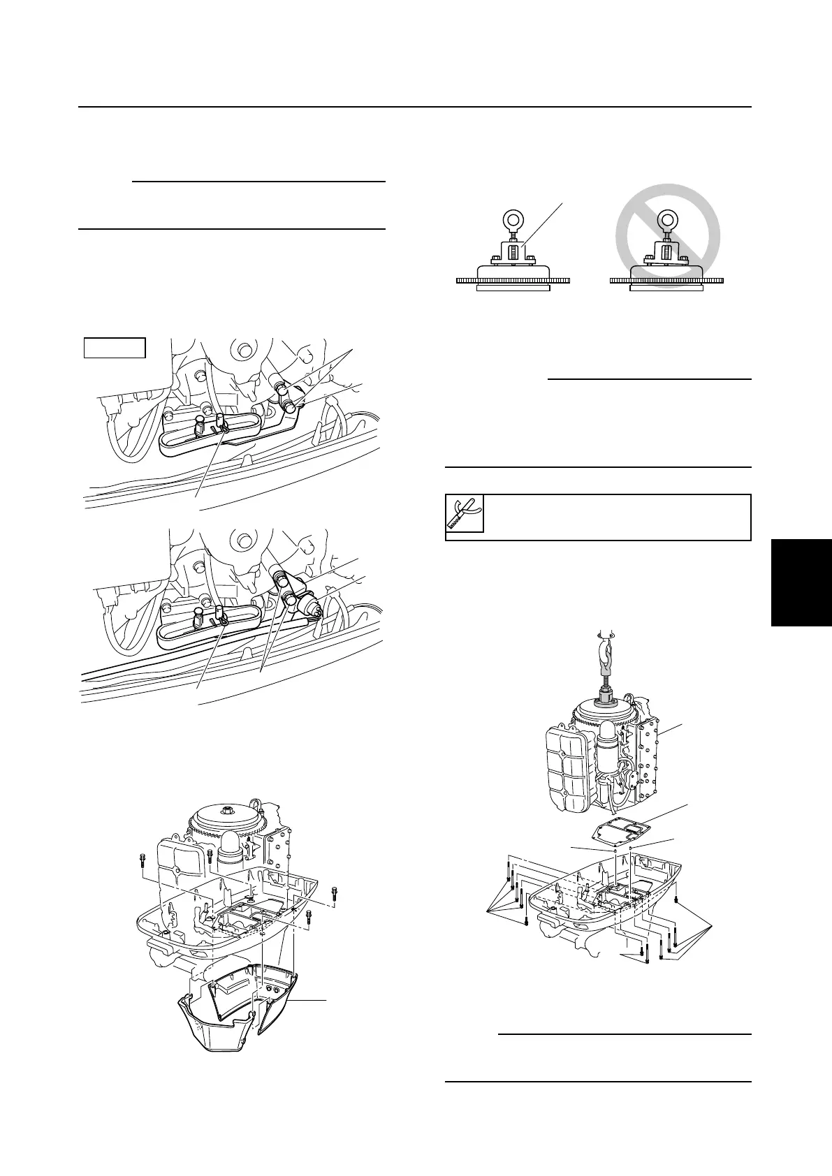
8. Install the special service tool f as
shown.
cC
To prevent damage to the engine or tools,
screw in the flywheel puller set bolts even-
ly and completely so that the flywheel
puller is parallel to the flywheel magnet.
9. Remove the bolts g and lift up the power
unit h, and then remove the dowels j
and gasket k.
10. Remove the fuel system and carburetors.
NOTE:
To remove the fuel system and carburetors,
refer to page 4-3 and 4-9.
5. Disconnect the fuel hose, and then
remove the choke knob.
NOTE:
To disconnect and remove the fuel hose and
choke link rod. Refer to page 4-3 and 4-9.
6. Remove the pin o and bolts p, bracket
a.
(EHD: pin o, bolts p, neutral switch s,
bracket a)
å ED, ET
∫ EHD
7. Remove the apron d.
Flywheel puller f: 90890-06521
6885J11_05 07.9.26 15:44 Page 13
 Loading...