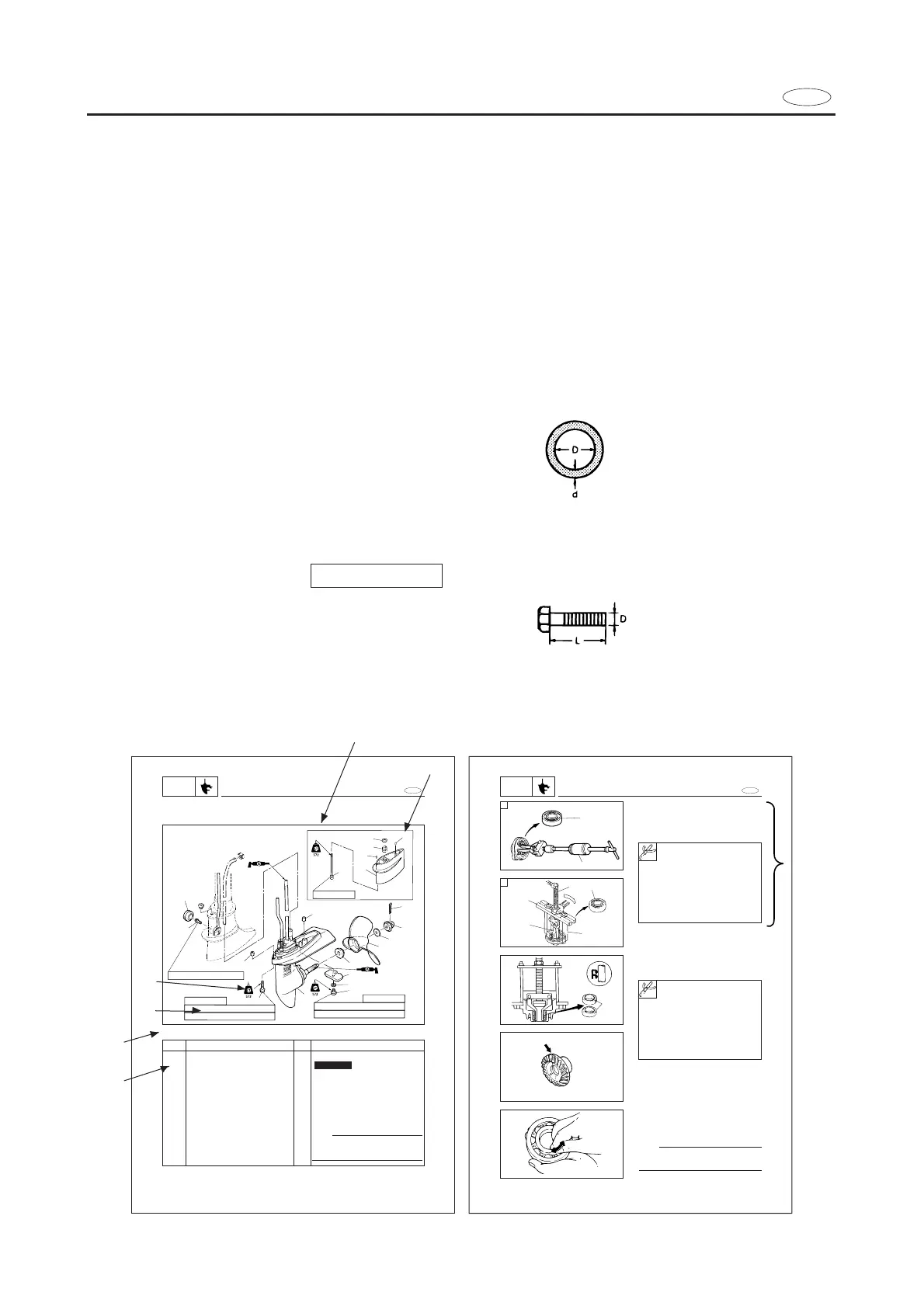
HOW TO USE THIS MANUAL
1 To help identify parts and clarify procedure steps, there are exploded diagrams at the
start of each removal and disassembly section.
2 Numbers are given in the order of the jobs in the exploded diagram. A circled number
indicates a disassembly step.
3 Symbols indicate parts to be lubricated or replaced (see “SYMBOLS”).
4 A job instruction chart accompanies the exploded diagram, providing the order of jobs,
names of parts, notes in jobs, etc.
Example:
O-ring size 39.5 x 2.5 mm: Inside diameter (D) x ring diameter (d)
5 Dimension figures and the number of parts, are provided for fasteners that require a
tightening torque:
Example:
Bolt or screw size 10 x 25 mm (2) : M10(D) x 25 mm (L) (2pieces)
6 Jobs requiring more information (such as special tools and technical data) are described
sequentially.
E
E
LOWER UNIT
LOWR
LOWER UNIT
EXPLODED DIAGRAM
zFor long
9
10
14
11
12
5
4
3
2
1
8
7
6
10 Nm (1.0 m•kg, 7.2 ft•lb)
11
13
17
16
15
M6 x 40 mm
M6 x 167 mm
15
M6 x 16 mm
14
1st 3 Nm (0.3 m•kg, 2.17 ft•lb)
2nd 8 Nm (0.8 m•kg, 5.8 ft•lb)
1st 3 Nm (0.3 m•kg, 2.17 ft•lb)
2nd 8 Nm (0.8 m•kg, 5.8 ft•lb)
6-1
REMOVAL AND INSTALLATION CHART
Step
1
2
3
4
5
6
7
8
9
10
Q’ty
1
1
1
1
1
1
1
1
1
1
Service points
Follow the left “Step” for removal.
NOTE
Set the shift lever to reverse position
and loosen the bolt (shift rod connec-
tor).
Not reusable
Procedure/Part name
LOWER UNIT REMOVAL
Cotter pin
Propeller nut
Washer
Propeller
Spacer
Bolt (anode)
Toothed washer (anode)
Anode
Grommet
Bolt (shift rod connector)
Lower casing cap oil seal removal
1. Remove:
9Oil seals 1
Lower casing cap/Propeller shaft bearing
removal
1. Remove:
9Ball bearing 1
A For USA and CANADA
B Except for USA and CANADA
E
LOWER CASING CAP ASS’Y
LOWR
3
4
1
6
5
1
6-12
Slide hammer set 2:
YB-06096
Stopper guide plate 3:
90890-06501
Bearing puller 4:
90890-06535
Bearing puller craw 5:
90890-06537
Stopper guide stand 6:
90890-06538
Slide hammer set:
YB-06096
Stopper guide plate:
90890-06501
Bearing puller:
90890-06535
Bearing puller craw:
90890-06537
Stopper guide stand:
90890-06538
SERVICE POINTS
Gears inspection
1. Inspect:
9Tooth
9Dog
Wear/Damage ® Replace.
Bearings inspection
1. Inspect:
9Bearing
Pitting/Rumbling ® Replace.
NOTE:
Turn the bearing by fingers and check the
bearing pitching
A
B