REMOVAL AND INSTALLATION CHART
Step
1
2
3
4
5
6
7
8
9
0
q
A
B
C
Q’ty
4
1
1
1
1
1
1
1
1
1
4
2
2
1
Service points
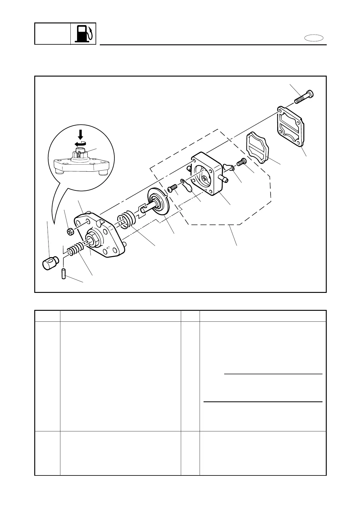
Follow the left “Step” for disassembly.
NOTE:
When removing the pin, push turn and
align the slot on the plunger with slit a
on the pump body.
Reverse the disassembly steps for installation.
Follow the left “Step” for disassembly.
Reverse the disassembly steps for installation.
Procedure/Part name
FUEL PUMP DISASSEMBLY
Screw
Fuel pump cover
Diaphragm
Fuel pump body ass’y
Pin
Plunger
Plunger spring
Diaphragm spring
Diaphragm
Fuel pump body 2
Nut
FUEL PUMP BODY DISASSEMBLY
Screw
Seat valve
Fuel pump body 1