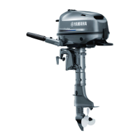
4. Inspect:
9Valve clearance
Use feeler gauge.
Out of specification ® Adjust.
5. Loosen:
9lock nut (rocker arm)
NOTE:
When loosening the locknut 6, lock the ad-
juster 7, otherwise the locknut 6 will not
loose.
Valve clearance
Intake
aa
: 0.10 ± 0.02 mm
(0.004 ± 0.0008 in)
Exhaust
bb
: 0.10 ± 0.02 mm
(0.004 ± 0.0008 in)
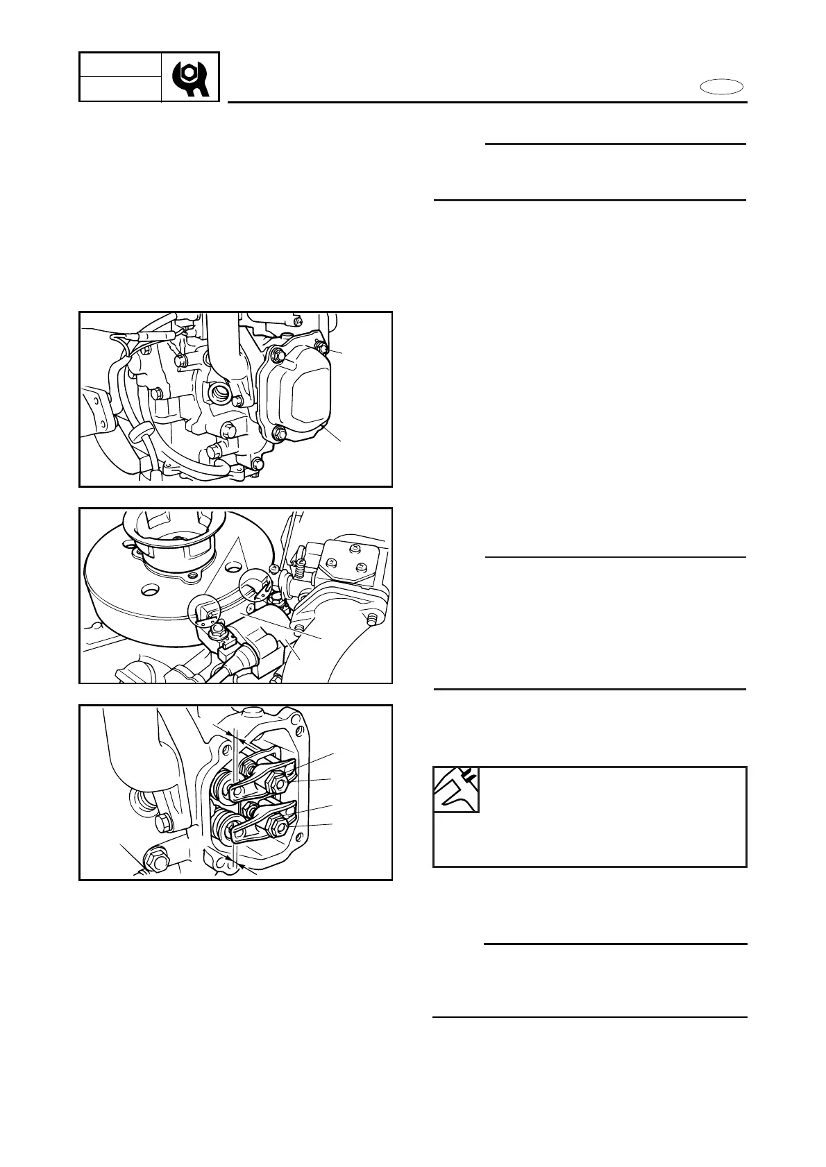
3. Position:
9Flywheel rotor
NOTE:
Turn the flywheel rotor ass’y clockwise and
check that the valves are fully closed with
there rocker arm in free position, and set
the magnet 3 on the flywheel rotor with
both core ends 4 of the ignitor ass’y 5
mated as shown.
Valve clearance
NOTE:
Adjust valve clearance, at room tempera-
ture, when piston is near T.D.C. in com-
pression process.
1. Remove:
9Top cowling
9Bolt (carrying handle)
9Carrying handle 2 (protector)
9Bottom cowling 2
9Bolt (recoil starter)
9Recoil starter ass’y
9Spark plug
2. Remove:
9Bolt (cylinder head cover) 1
9Cylinder head cover 2
9Gasket (cylinder head cover)