12
9
9
7
8
18
11
10
6
5
13
17
15
10
10
3
4
16
14
2
1
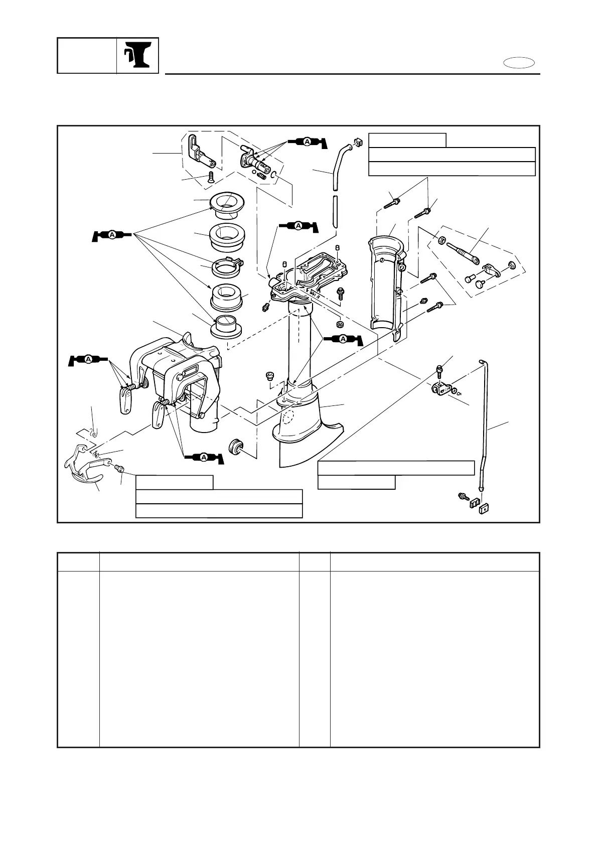
M6 x 25 mm
4.5 Nm (0.45 m•kg, 3.25 ft•lb)
1st 3 Nm (0.3 m•kg, 2.17 ft•lb)
2nd 8 Nm (0.8 m•kg, 5.8 ft•lb)
M6 x 10 mm
1st 3 Nm (0.3 m•kg, 2.17 ft•lb)
2nd 8 Nm (0.8 m•kg, 5.8 ft•lb)
M6 x 35 mm
7-7
REMOVAL AND INSTALLATION CHART
Step
1
2
3
4
5
6
7
8
Q’ty
1
1
1
1
1
1
2
1
Service points
Follow the left
“
Step” for removal.
Refer to “POWER UNIT” section in Chapter 5
.
Refer to “LOWER UNIT” section in Chapter 6
.
Refer to “STEERING HANDLE” section
.
Procedure/Part name
UPPER CASE ASS’Y REMOVAL
Power unit
Lower unit
Steering handle
Screw (shift lever)
Shift lever ass’y
Bolt (shift shaft)
Shift rod ass’y
Water tube
Steering friction screw ass’y
Bolt (tilt lock plate)
Tilt lock plate