REMOVAL AND INSTALLATION CHART
Step
1
2
3
4
5
6
Q’ty
1
1
2
1
1
1
Service points
Follow the left “Step” for removal.
NOTE:
After connecting the fuel filter, clamp
the choke wire to fuel hose using the
hose clamp (s) a.
NOTE:
In this installation, make sure the arrow
mark face the fuel pump side.
Reverse the removal steps for installation.
Not reusable
Procedure/Part name
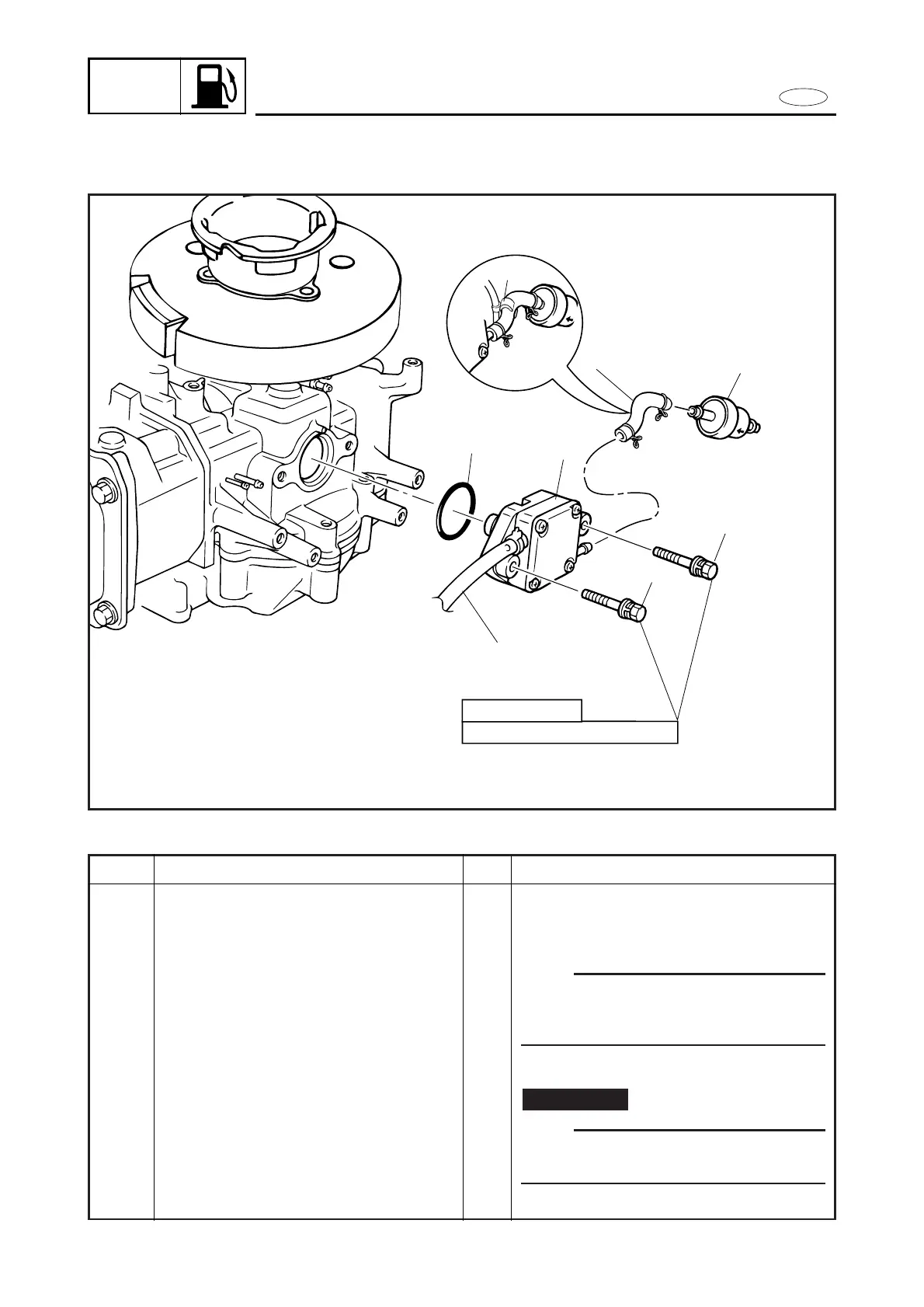
FUEL PUMP AND FUEL FILTER
REMOVAL
Fuel hose (fuel pump-to-carburetor)
Fuel hose (fuel filter-to-fuel pump)
Bolt with washer
Fuel pump ass’y
O-ring
Fuel filter