1
2
3
4
6
7
7
5
8
9
10
11
11
13
14
12
12
8 Nm (0.8 m•kg, 5.8 ft•lb)
8 Nm (0.8 m•kg, 5.8 ft•lb)
M6 x 25 mm
M6 x 90 mm
2
5
3
4
8
1
a
b
c
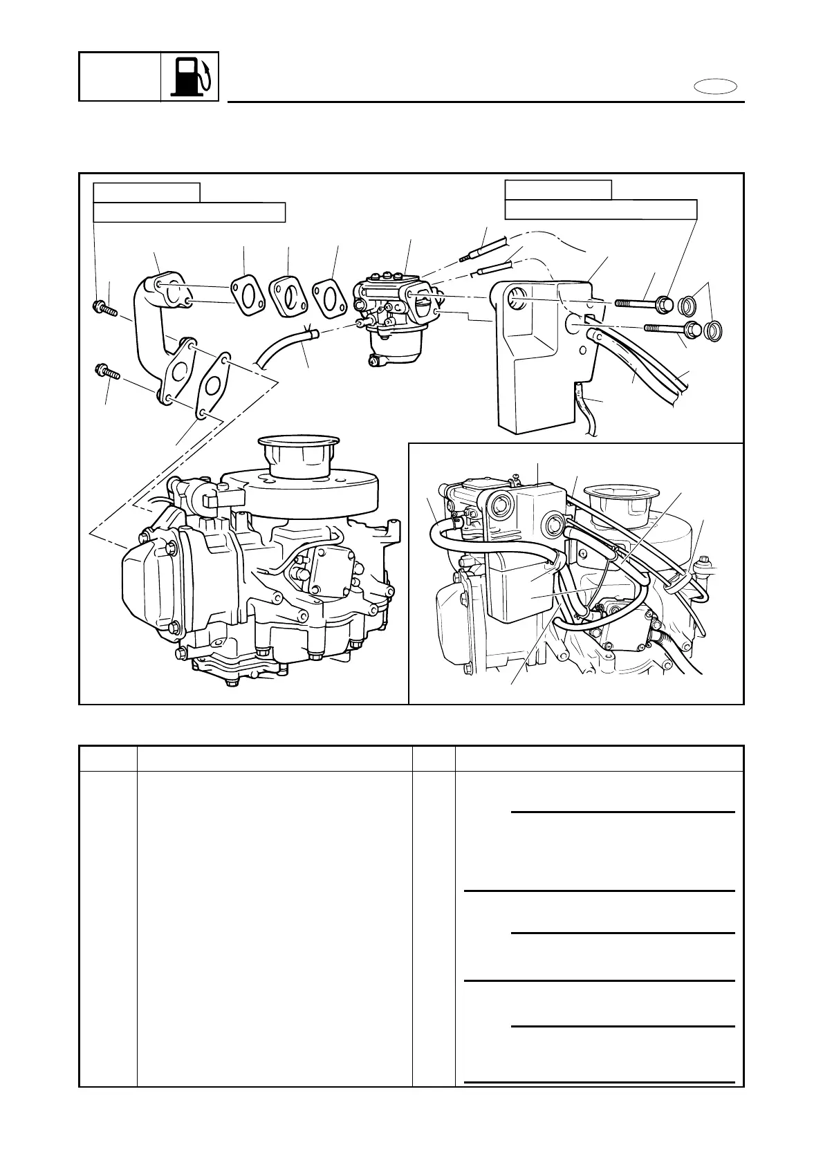
REMOVAL AND INSTALLATION CHART
Step
1
2
3
4
5
Q’ty
1
1
1
1
1
Service points
Follow the left “Step” for removal.
NOTE:
9Disconnect the wire and cable from carbu-
retor side.
9Clamp the wire and cable with the cable
clamp c, after connected.
f 9 mm
NOTE:
Clamp the fuel hose and breather hose
with the hose clamp b, after connected.
f
7 mm
NOTE:
When connecting the fuel hose, pass the
fuel hose through the clamp a on the
intake silencer.
Procedure/Part name
INTAKE SYSTEM REMOVAL
Choke wire
Throttle cable
Breather hose 1
Breather hose 2
Fuel hose