E
CYLINDER HEAD AND PUSH ROD
POWR
CYLINDER HEAD AND PUSH ROD
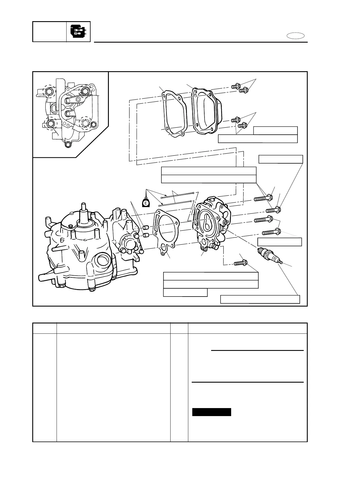
EXPLODED DIAGRAM
4
3
2
2
6
6
1
5
10
8
11
11 Nm (1.1 m•kg, 8.0 ft•lb)
25 Nm (2.5 m•kg, 18 ft•lb)
1st 6 Nm (0.6 m•kg, 4.3 ft•lb)
2nd 12 Nm (1.2 m•kg, 8.7 ft•lb)
2
4
3
1
1st 15 Nm (1.5 m•kg, 10.8 ft•lb)
2nd 30 Nm (3.0 m•kg, 22 ft•lb)
M6 x 12 mm
M8 x 60 mm
M8 x 40 mm
M6 x 45 mm
9
7
5-11
REMOVAL AND INSTALLATION CHART
Step
1
2
3
4
5
6
7
Q’ty
1
4
1
1
1
3
1
Service points
Follow the left “Step” for removal.
NOTE:
9Cylinder head maintenance is possible
with the power unit mounted.
9Loosen the locknut (rocker arm), to
install the cylinder head and push rod.
Not reusable
Procedure/Part name
CYLINDER HEAD AND PUSH ROD
REMOVAL
Spark plug
Bolt (cylinder head cover)
Cylinder head cover
Gasket (cylinder head cover)
Bolt (cylinder head)
Bolt (cylinder head)
Bolt (cylinder head)