5-10
REMOVAL AND INSTALLATION CHART
Step
1
2
3
4
5
Q’ty
1
7
1
2
1
Service points
Follow the left “Step” for removal.
Refer to “BRACKET UNIT” in chapter 7.
Refer to “FUEL TANK AND FUEL COCK”
section in Chapter 4.
Refer to “RECOIL STARTER” section.
Loosen the adjuster for the crankcase side.
Reverse the removal steps for installation.
Not reusable
Procedure/Part name
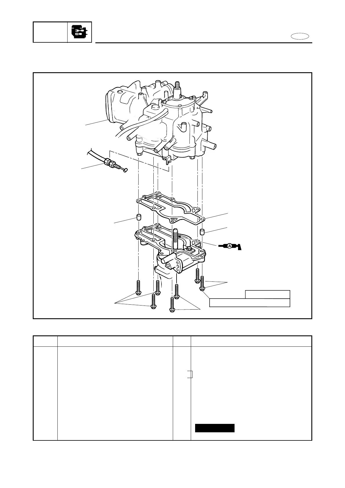
POWER UNIT REMOVAL
Carrying handle and bottom cowling
Fuel tank and fuel cock ass’y
Throttle cable
Recoil starter ass’y
Start-in-gear protection cable
Bolt (power unit)
Power unit
Dowel pin (upper casing)
Gasket (upper casing)