E
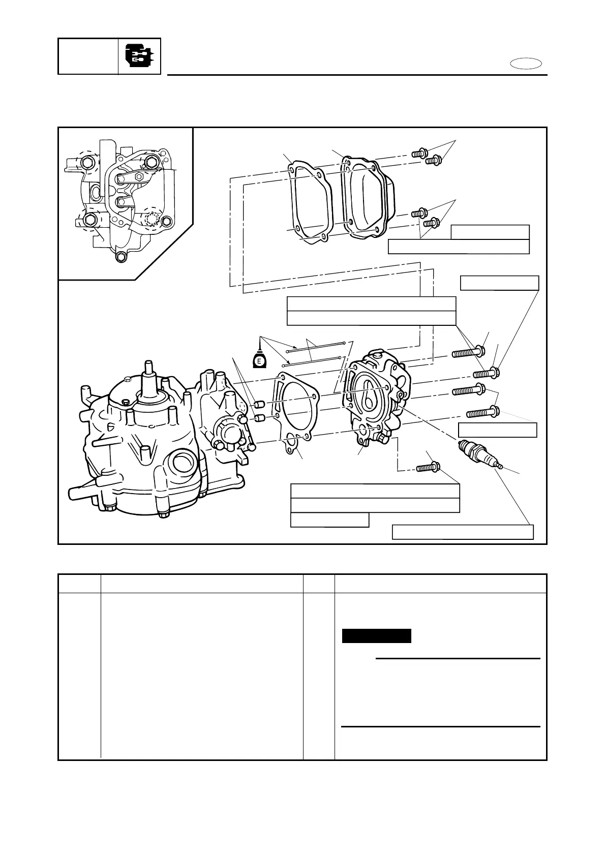
CYLINDER HEAD AND PUSH ROD
POWR
EXPLODED DIAGRAM
4
3
2
2
6
6
1
5
10
8
11
11 Nm (1.1 m•kg, 8.0 ft•lb)
25 Nm (2.5 m•kg, 18 ft•lb)
1st 6 Nm (0.6 m•kg, 4.3 ft•lb)
2nd 12 Nm (1.2 m•kg, 8.7 ft•lb)
2
4
3
1
1st 15 Nm (1.5 m•kg, 10.8 ft•lb)
2nd 30 Nm (3.0 m•kg, 22 ft•lb)
M6 x 12 mm
M8 x 60 mm
M8 x 40 mm
M6 x 45 mm
9
7
5-12
REMOVAL AND INSTALLATION CHART
Step
8
9
10
11
Q’ty
1
2
1
2
Service points
Refer to “SERVICE POINTS” section.
NOTE:
9Clean the cylinder head and cylinder
body mating surface thoroughly.
9When installing the gasket, do not
touch it with oily or greasy hands and
do not apply any sealant.
Reverse the removal steps for installation.
Not reusable
Procedure/Part name
Cylinder head ass’y
Push rod
Gasket (cylinder head)
Dowel pins