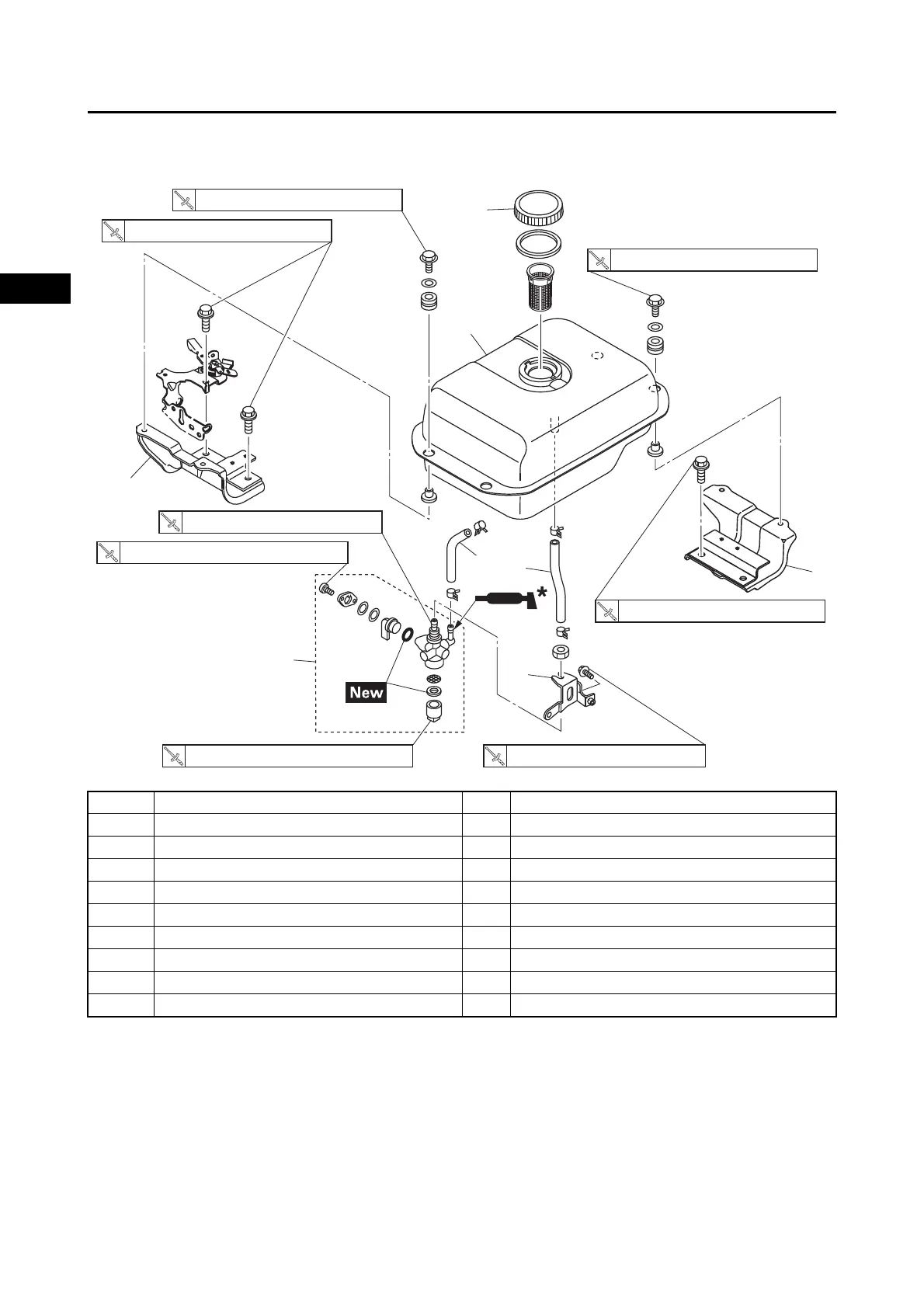
FUEL TANK (Equipped models)
3-6
1
2
3
4
5
6
7
8
9
10
ENGINE
MX360C46A5
*P-80®GRIP-IT
When installing the fuel hose, use a brush to apply a small amount of P-80®GRIP-IT as an insertion
auxiliary agent to the nipple of the installation-destination pipe.
Order Job/Parts to remove Q’ty Remarks
Removing the fuel tank Remove the parts in the order listed.
1 Fuel hose 1 1 Turn the fuel cock lever to the “OFF” position.
2 Fuel hose 2 1
3Fuel tank 1
4 Fuel tank stay 1 1
5 Fuel tank stay 2 1
6 Fuel tank cap 1
7 Fuel cock assembly 1
8 Fuel cock stay 1
1
2
3
4
5
6
7
8
1.3 N・m (0.13 kgf・m, 0.95 lb・ft) 7 N・m (0.7 kgf・m, 5.2 lb・ft)
10 N・m (1.0 kgf・m, 7.4 lb・ft)
10 N・m (1.0 kgf・m, 7.4 lb・ft)
29 N・m (2.9 kgf・m, 21 lb・ft)
29 N・m (2.9 kgf・m, 21 lb・ft)
0.8 N・m (0.08 kgf・m, 0.59 lb・ft)
6 N・m (0.6 kgf・m, 4.4 lb・ft)