GOVERNOR
3-23
1
2
3
4
5
6
7
8
9
10
ENGINE
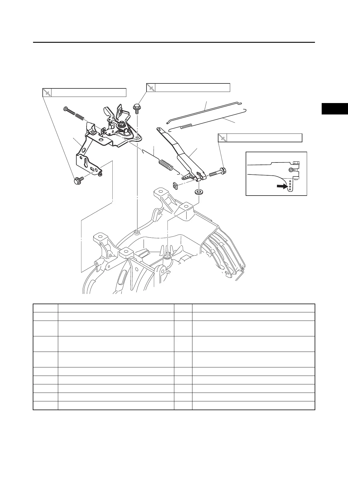
THROTTLE LEVER ASSEMBLY (MX360C46A5/MX360AA6A0/MX360AA6A5/
MX360AA6A6)
Order Job/Parts to remove Q’ty Remarks
Removing the throttle lever assembly Remove the parts in the order listed.
Fuel tank
Refer to “FUEL TANK (Equipped models)” on
page 3-5.
Fuel tank stay
Refer to “FUEL TANK (Equipped models)” on
page 3-5.
Engine switch and oil warning unit
Refer to “ENGINE SWITCH AND OIL
WARNING UNIT” on page 3-31.
1 Spring 1
2 Link rod 1
3 Spring 1
4 Governor arm 1
5 Throttle lever assembly 1
7 N・m (0.7 kgf・m, 5.2 lb・ft)
8 N・m (0.8 kgf・m, 5.9 lb・ft)
1
2
3
4
5
7 N・m (0.7 kgf・m, 5.2 lb・ft)