7-21
1
2
3
4
5
6
7
8
9
10
SPECIFICATIONS
WIRE ROUTING DIAGRAM
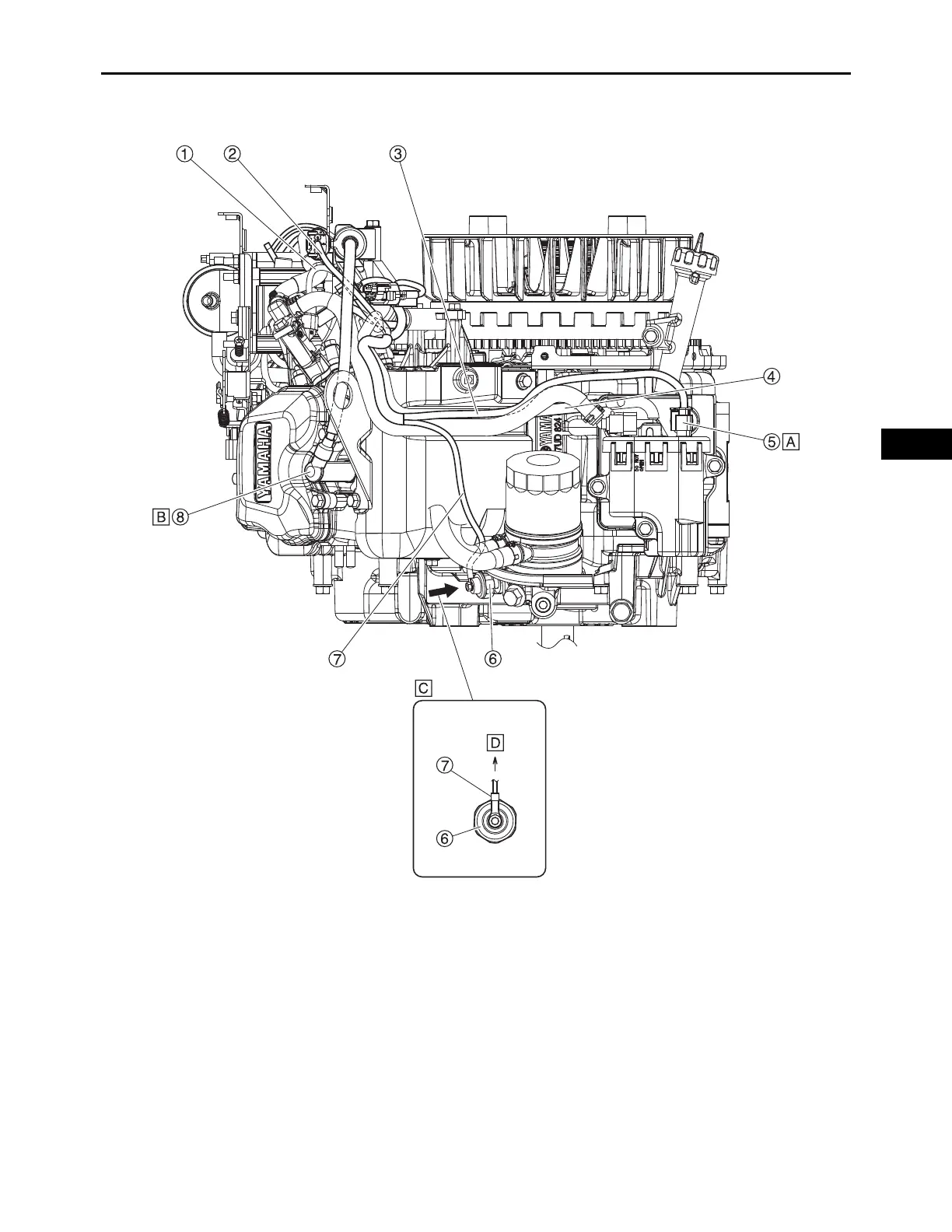
1. Fuel injector #2 lead 5. High-pressure fuel pump coupler
2. Ignition coil #2 lead 6. Oil pressure switch
3. High-pressure fuel pump lead 7. Oil pressure switch lead
4. Purge hose 8. Spark plug cap
A. The high-pressure fuel pump coupler should be laid along the purge hose.
B. Install the spark plug cap in the direction shown in the illustration.
C. Oil pressure switch lead routing direction
D. Direction of upper surface of the engine