7-20
1
2
3
4
5
6
7
8
9
10
SPECIFICATIONS
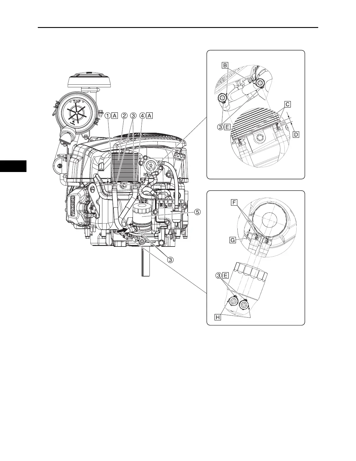
WIRE ROUTING DIAGRAM
1. Oil hose 1 4. Oil hose 2
2. Oil cooler 5. Oil filter
3. Hose clamp
A. Insert the oil hose all the way into the oil cooler.
B. Face the projection inward.
C. Install the white painted portion in the direction shown in the illustration.
D. 8–12 mm (0.31–0.47 in)
E. Install the hose clamp in the direction shown in the illustration.
F. Install the yellow painted portion in the direction shown in the illustration.
G. 2.0–4.0 mm (0.08–0.16 in)
H. Face the projection outward.