7-24
1
2
3
4
5
6
7
8
9
10
SPECIFICATIONS
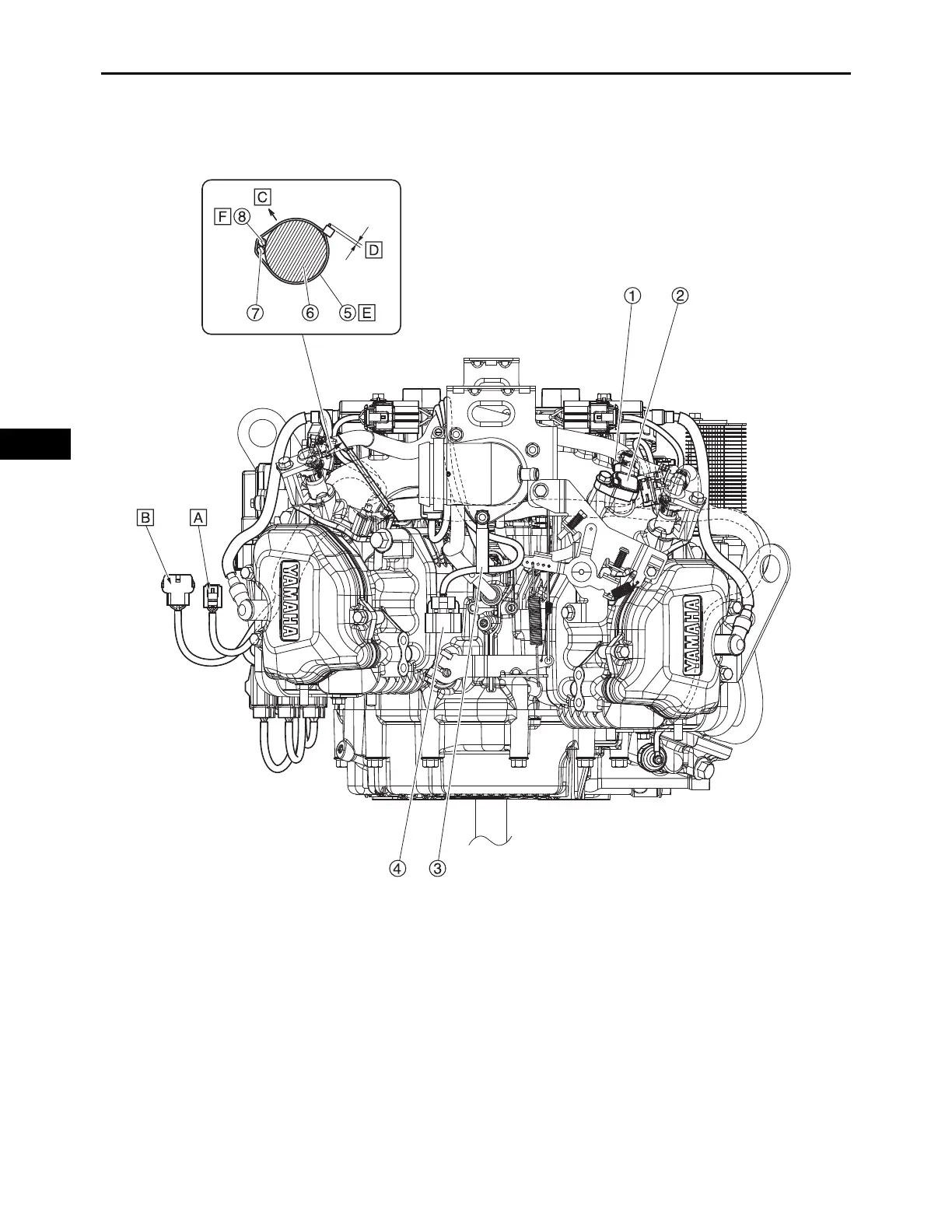
WIRE ROUTING DIAGRAM
1. Manifold absolute pressure sensor coupler 5. Plastic locking tie
2. Manifold absolute pressure sensor 6. Inlet manifold
3. Clamp 7. Ignition coil #1 lead
4. O
2
sensor coupler 8. Fuel injector #1 lead
A. FI diagnostic tool coupler
B. Main switch coupler
C. Direction of upper surface of the engine
D. Allowance 2.0 mm (0.08 in) or less
E. Install the plastic locking tie as shown in the illustration.
F. • Install the leads so that they do not overlap each other.
• The leads should not interfere with the side of the fan case.