11 LED Indicator on Each Circuit Board
FS100 11.2 7-Segment LED Indicator on the Main CPU Circuit Board
(CPU201R)
11-5
11.2.2 Status of 7-Segment LED Indicator at Control Power Start-up (one digit)
11.2.3 Status of 7-Segment LED Indicator at Hardware Error Occurrence
When the hardware error is detected during the operation, the error is
indicated with 4-digit numbers with the letter [H] at its head.
Indication spec.:
Repeat of [ H ]
→ [0] → [0] → [0] → [1] → [.]
Turn the power supply OFF and ON again when the above mentiond
numbered error is indicated by the 7-Segment.
Replacement of the controller is requied if the the error occurs again.
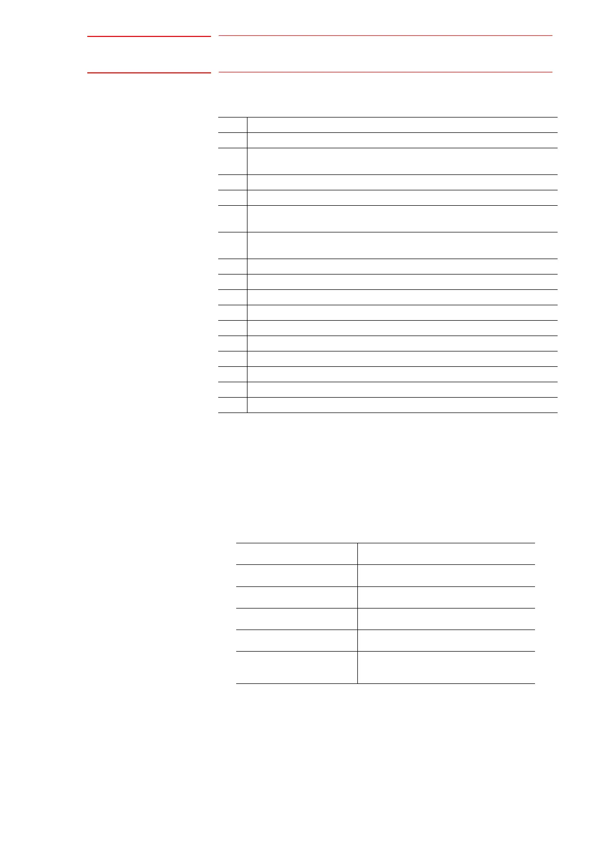
Error Status
1 The system program has started.
2 Starts verifying the existence of other circuit boards.
(Verifies the start-up of the booting program.)
3 Starts the system program transmission.
4 Sends the request of the system program start-up.
5 Starts verifying the existence of other circuit boards.
(Verifies the start-up of the system program.)
6 Acquires hardware information, etc. of other circuit boards.
(Verifies the IO board status, SERVO IF, and so on.)
7 Starts the CMOS data transmission.
8 Sends the pre-online request.
9 Waits for MIII communication synchronization.
A
b Sends the start-up request of on-line system.
C The on-line system has started. (Starts up the initialization task.)
d Processes of the system setup completion. (Servo ON enabled)
E Alarm occurs at the system setup.
F The maintenance mode is starting up.
P The system setup PP/SWP unconnected.
Alarm No.
H0001 MAC address eorror
H0002 Power lost error when start-up
H0003 Watchdog error when start-up
H0004 Interrupt clear impossible
H0005 Initialization of SERVO communication
error