1.3 System Configuration Example
1-5
1.3 System Configuration Example
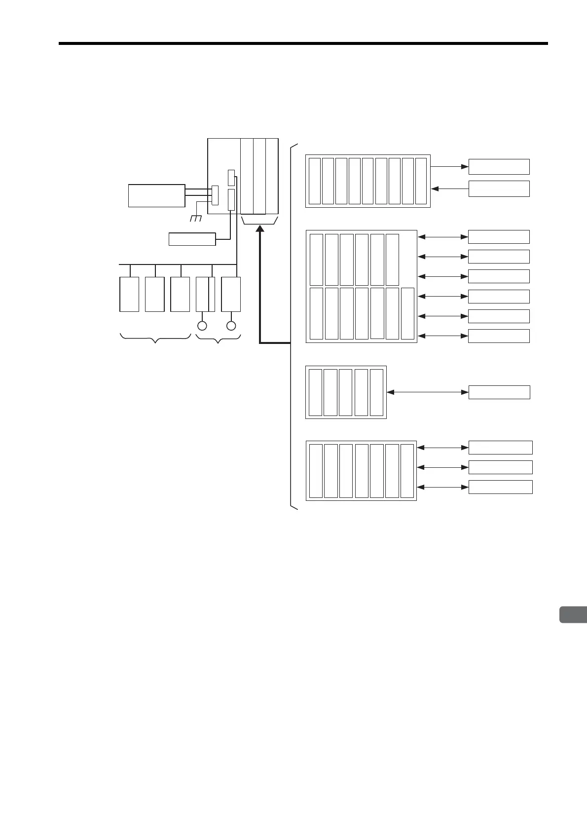
The following diagram shows an example of system configuration.
For the details on the system configuration example, refer to 4.1.2
System Configuration
on page 4-3.
Use the connecting cables and connectors recommended by Yaskawa. Always check the device to be used
and select the correct cable for the device.
Different SERVOPACKs are connected to MECHATROLINK-Ι (4 Mbps), MECHATROLINK-ΙΙ (10 Mbps), and
MECHATROLINK-ΙΙΙ (100 Mbps). Refer to 1.4.1 Devices Connectable to MECHATROLINK-I/II on page 1-6,
1.4.2 Devices Connectable to MECHATROLINK-III on page 1-8 and select the appropriate SERVOPACKs.
If devices compatibe with MECHATROLINK-Ι and with MECHATROLINK-ΙΙ are used together, make the set-
tings for MECHATROLINK-Ι.
The user must supply the 24-VDC power supply.
When connecting SERVOPACKs via MECHATROLINK, connect the overtravel, zero point return deceleration
limit switch, and external latch signals to the SERVOPACKs. For connection, refer to the SERVOPACK’s man-
ual.
24-VDC
power supply
I/O Modules for
MECHATROLINK
SGDS
M
IO2310
PL2900
PL2910
Optional Modules
NS115
SGDH
M
MP2300
MECHATROLINK-II
Servos
External I/O
266IF-02
217IF-01
218IF-01
218IF-02
260IF-01
261IF-01
263IF-01
264IF-01
265IF-01
266IF-01
Communications Modules
SVA-01
SVB-01
PO-01
SVC-01
MPU-01
Motion Modules
MPALL00-0
MPAL000-0
AFMP-01
MPANL00-0
AFMP-02-C/-CA
MPAN000-0
Other Modules (including those from other manufacturers)
External outputs
Extrenal inputs
RS-232C
Ethernet
DeviceNet
PROFIBUS
RS422/485
215 communications
SERVOPACK
AnyWire
A-net/A-link
I/O Modules
CC-Link
LIO-01
LIO-02
LIO-04
LIO-05
DO-01
LIO-06
AI-01
AO-01
CNTR-01
262IF-01
267IF-01
215AIF-01
MPCUNET-0