3.7Forming a Protective Sequence
127
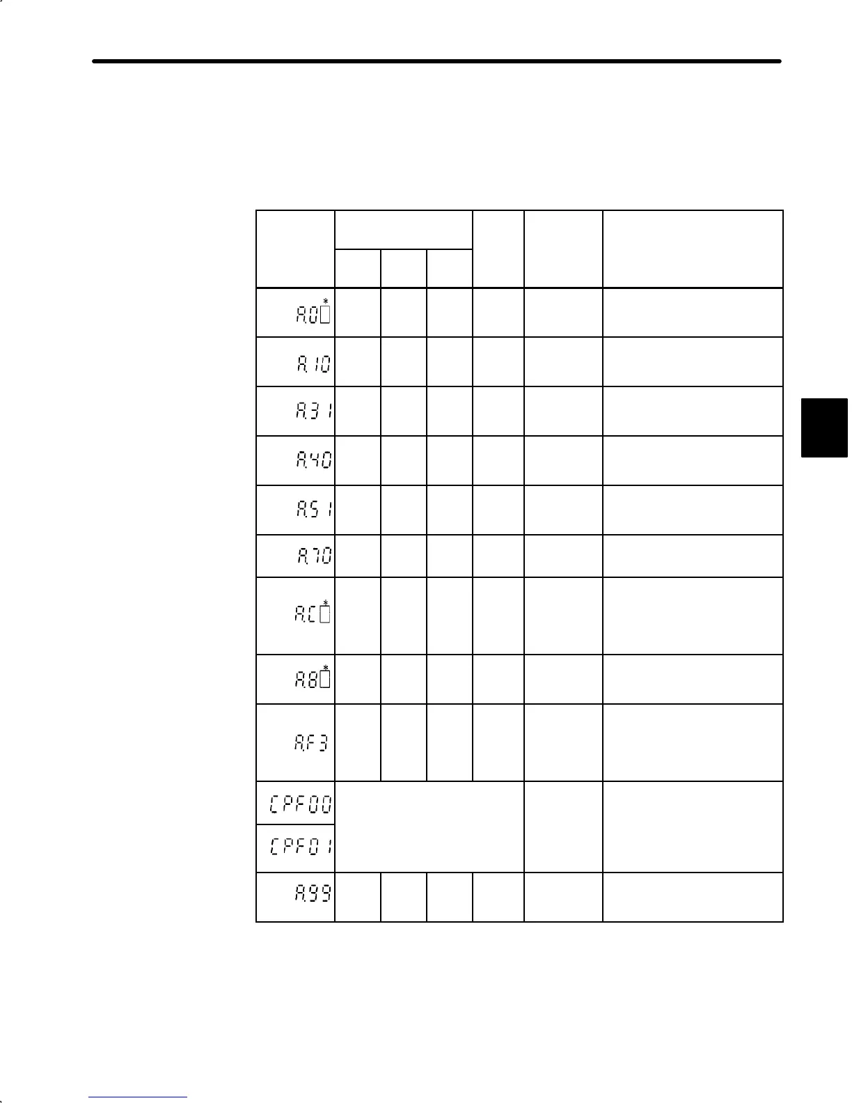
4) Relationship between Alarm Display and Alarm Code Output
Alarm Display and Alarm Code Output:
Alarm
Alarm Code Output
Servo
Alarm
Display
ALO1 ALO2 ALO3
Out-
put
arm
ype
arm
escr
pt
on
¢
¢ ¢ ¢
User
constant
error
An absolute encoder error oc-
curred or user constant is
faulty.
○
¢ ¢ ¢
Overcurrent Overcurrent flowed thorough
the main circuit.
Servopack overheated.
○ ○
¢ ¢
Position
error pulse
overflow
The number of pulses in error
counter has exceeded the
preset value.
¢
¢
○
¢
Overvoltage Main circuit DC voltage has
exceeded approximately
420 V.
○
¢
○
¢
Overspeed Motor speed has exceeded
the maximum allowable
speed.
○ ○ ○
¢
Overload Motor and Servopack are
overloaded.
○
¢
○
¢
Overrun
Disconnec-
tion of PG
signal line
Overrun occurred due to mo-
tor or encoder signal wiring
faults.
Encoder signal line is discon-
nected.
¢
¢ ¢ ¢
Absolute
encoder er-
ror
Absolute encoder is faulty.
¢
○
¢ ¢
Power loss
alarm
After power was turned OFF,
power was turned ON again
within power holding time.
Power loss occurred during
operation.
Digital
Operator
transmis-
Communication error oc-
curred between Digital Opera-
tor and Servo
ack.
Undefined
sion error
.
¢
¢ ¢
○
No error
○ : Output transistor is ON
¢ : Output transistor is OFF
* : Displays an alarm category number.
For details, refer to Appendix E List of Alarm Displays.
3
 Loading...


