5.1 Selecting aΣ -Series Servo
211
3) Machine Data Table
Fill out the machine data table below as an aid to selecting the drive system. When the
machine data table is complete, use the servomotor sizing software to select the motor
capacity.
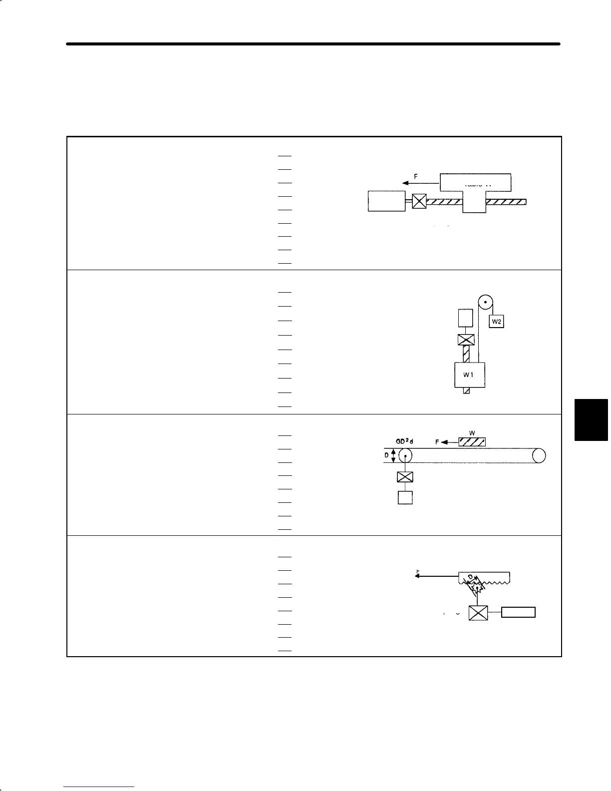
1) Ball Screw Horizontal Axis
Load mass W kg (lb)
Thrust F kg (lb)
Coefficient of friction
µ
Table W
Overall efficiency
η
Gear ratio R (= Nm/Nl)
Motor
Ball screw
Gear+coupling GD
2
g
kg¡cm
2
(lb¡in
2
.)
Gear+coupling
Ball screw pitch P mm (in.)
GD
2
g
Ball screw diameter D mm (in.)
Ball screw length L mm (in.)
2) Ball Screw Vertical Axis
Load mass W
1
kg (lb)
Counterweight W
2
kg (lb)
Coefficient of friction
µ
Motor
Overall efficiency
η
Gear ratio R (= Nm/Nl)
GD
2
g
Gear+coupling GD
2
g
kg¡cm
2
(lb¡in
2
.)
Ball screw pitch P mm (in.)
Ball screw diameter D mm (in.)
Ball screw length L mm (in.)
Ball screw
3) Timing Belt
Load mass W kg (lb)
Pulley
Thrust F kg (lb)
Coefficient of friction
µ
Overall efficiency
η
Gear+couplin
Timing belt
Gear ratio R (= Nm/Nl)
GD
2
g
Gear+coupling GD
2
g
kg¡cm
2
(lb¡in
2
.)
Pulley GD
2
d
kg¡cm
2
(lb¡in
2
.)
Motor
Pulley diameter D mm (in.)
4) Rack and Pinion
Load mass W kg (lb)
Thrust F kg (lb)
W
Coefficient of friction
µ
Rack
Overall efficiency
η
Pinion
Gear ratio R (= Nm/Nl)
Gear+coupling
Motor
Gear+coupling GD
2
g
kg¡cm
2
(lb¡in
2
.)
GD
2
g
Pinion diameter D mm (in.)
Pinion thickness t mm (in.)
5
 Loading...


