5.2SGM Servomotor
233
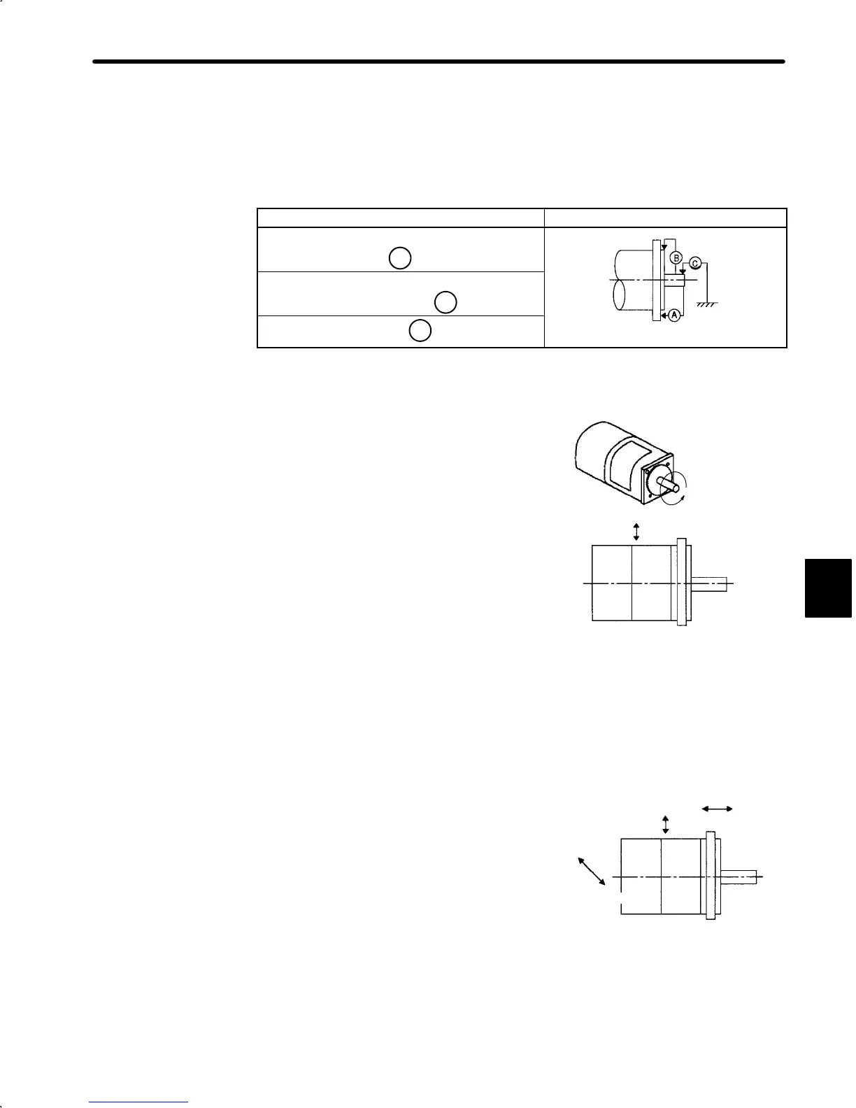
2) Mechanical Tolerance
The tolerances of the SGM and SGMP Servomotor output shaft and installation are
shown in the table below.
Tolerance (T.I.R.) Reference Diagram
Perpendicularity between flange
face and output shaft
A
0.04mm
(0.0016in.)
Mating concentricity of flange O.D.
B
0.04mm
(0.0016in.)
Run-out at end of shaft
C
0.02mm
(0.00079in.)
Note T.I.R. = Total Indicator Reading
3) Direction of Motor Rotation
Positive rotation of the servomotor is counter-
clockwise, viewing from the load.
4) Impact Resistance
Mount the servomotor with the axis horizontal.
The servomotor must withstand the following ver-
tical impacts.
• Impact Acceleration: 98 m/s
2
(10 G)
• Number of Impacts: 2
NOTE In SGM and SGMP Servomotors, an accurate detector is attached to the shaft at the opposite
end from the load.
Avoid applying impacts directly to the shaft as these may damage the detector
5) Vibration Resistance
Mount the servomotor with the axis horizontal.
The servomotor must withstand the following
vibration accelerations in three directions: verti-
cal, transverse, and longitudinal.
• Vibration Acceleration: 24.5 m/s
2
(2.5 G)
5
Vertical
Horizontal shaft
Vertical
Horizontal
shaft
Longitudinal
Transverse
 Loading...


