SERVO SELECTION AND DATA SHEETS
5.4.1 Servomotor Dimensional Drawings
282
3) “08AW14” and “08AW16” have a keyed shaft. The keyway complies with JIS B
1301-1976 (precision). A straight key is supplied.
4) The quoted allowable radial load is the value at a position 35 mm (1.38 in.) from the mo-
tor mounting surface.
5) Conforms to IP55 protective structure (except connector and output shaft faces).
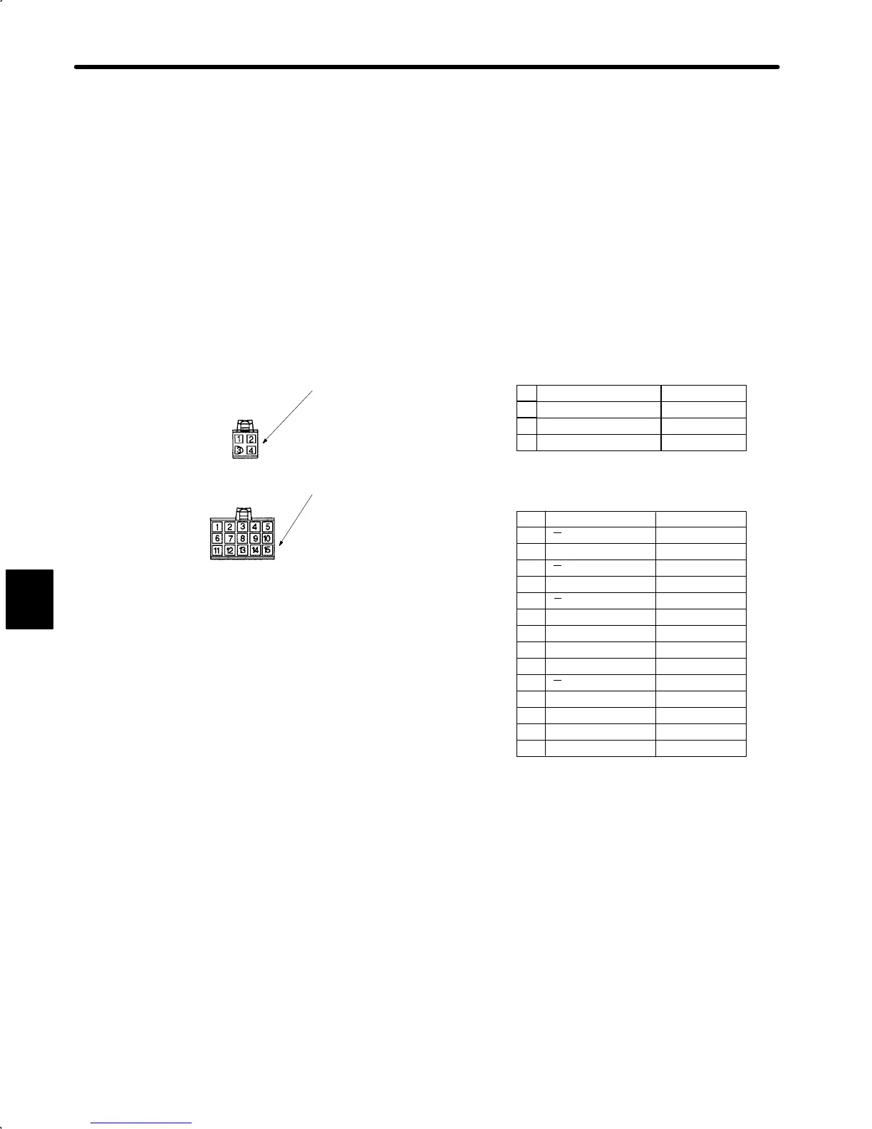
• Details of Motor and Encoder Plugs (Common for 100 W (0.13 HP) to 750 W (1.01 HP))
Socket 170362-1 or 170366-1
U phase Red
V phase White
W phase Blue
FG Green/Yellow
Pin 170360-1 or 170364-1
Cap 172159-1
Motor Wiring Specifications
Absolute Encoder Wiring Specifications
A channel output Blue
A
channel output White/Blue
B channel output Yellow
B
channel output White/Yellow
Green
White/Green
Black
Red
FG (Frame Ground) Green/Yellow
Plug: 172171-1 (AMP)
Pin: 170359-1 or 170363-1
Plug : 172167-1 (AMP)
Connected to
Connected to
Cap :172163-1
Socket: 170361-1 or 170365-1
1
2
3
4
1
2
3
4
5
6
7
8
13
14
15
S channel output
S
channel output
Purple
White/Purple
(Capacitor reset) (Gray)
Reset White/Gray
0V(battery)
3.6V(battery)
White/Orange
Orange
Terminal to discharge capacitor for product dispatch. Do not
use.
*
*
Z channel output
Z
channel output
0V (power supply)
+5 V(power supply)
9
10
11
(12)
Motor Plug
Encoder Plug
5
cont.
 Loading...


