SERVO SELECTION AND DATA SHEETS
5.4.1 Servomotor Dimensional Drawings
288
6) Conforms to IP55 protective structure (except connector and output shaft faces).
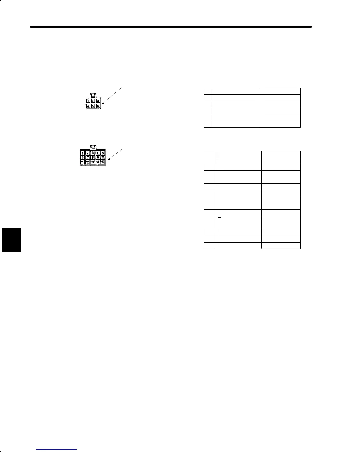
• Details of Motor and Encoder Plugs (Common for 100W (0.13 HP) to 750 W (1.01 HP))
A channel output Blue
A
channel output White/Blue
B channel output Yellow
B
channel output White/Yellow
Green
White/Green
Black
Red
FG (Frame Ground) Green/Yellow
Z
channel output
Z channel output
0 V (power supply)
+5 V (power supply)
1
2
3
4
5
6
7
8
9
10
11
(12)
13
14
15
S channel output
S
channel output
Purple
White/Purple
(Capacitor reset) (Gray)
Reset White/Gray
0V(battery)
3.6V(battery)
White/Orange
Orange
Socket 170362-1 or 170366-1
U phase Red
V phase White
W phase Blue
FG Green/Yellow
Pin 170360-1 or 170364-1(1 to 4pin)
170359-1 or 170363 (5 to 6 pin)
(17360-1 or 17364-1:only 750W)
Cap 172160-1
Motor Wiring Specifications
Absolute Encoder Wiring Specifications
Plug: 172171-1 (AMP)
Pin: 170359-1 or 170363-1
Plug : 172168-1 (AMP)
Connected to
Connected to
Cap :172163-1
Socket: 170361-1 or 170365-1
1
2
3
4
5
6
Brake terminal
Brake terminal
Black
Black
Terminal to discharge capacitor for product dispatch. Do not
use.
*
*
Motor Plug
Encoder Plug
5
cont.
 Loading...


